With the silos completed, I temporarily placed each one in
place so that I could lay out the main auger trunk line running
the length of the silo base, and the locations of the chutes
that connected each silo to the main auger. The augers them-
selves were assembled from ¼” styrene tubing with a piece of
.020” thick by .40” wide piece of strip styrene attached to the
tubing lengthwise. Two pieces of .030” by .040” styrene were
placed on either side of the tube, and a strip of .010” styrene
was wrapped around the tubing in a U-shape [20 and 21]. The
wrapped styrene required several applications of body putty
and sanding to get a smooth seam, but ultimately I wasn’t wor-
ried about being perfect, since the detail was hidden beneath
the silos and bracing.
Once the main auger was complete, I followed the same pro-
cess, with slightly smaller .219”
tubing for the chutes that run
perpendicular to the main auger
Agway Feed Mill - 13
beneath each silo, and cut each chute into lengths 1.15” long.
The assembled auger and chutes were then placed on the silo
base so I could construct the supports using .100” I-beams.
Three pieces of .100” I-beams were used to support each chute
assembly while .125” I-beams were used for the main auger
assembly, one on either side of the chutes [20].
Once the entire assembly was completed, I went ahead with
painting and weathering, since doing this after the silos were in
place wouldn’t be possible.
After the auger assembly was complete and permanently glued
in place, the last step was adding .020” by .060” diagonal brac-
ing between each silo support, and horizontal .060” angle at
the base of each column.
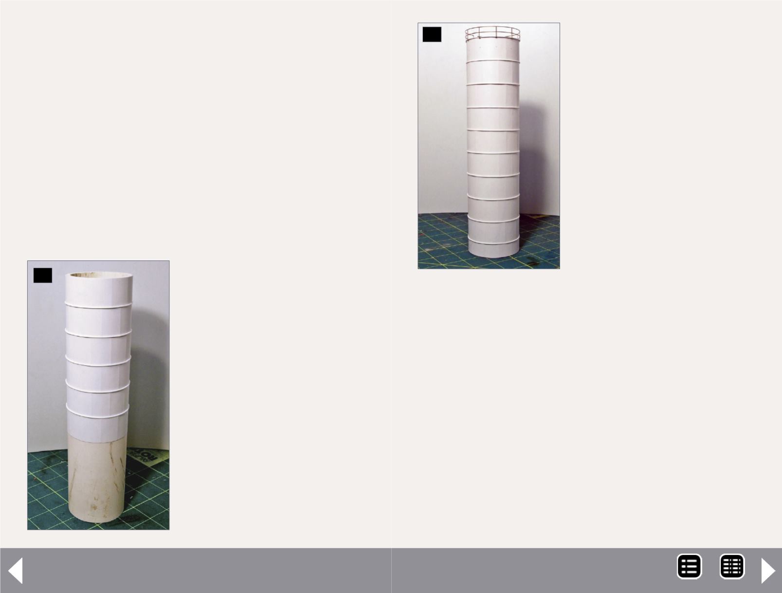
24. In this view, the styrene
panels are being applied to
the end silo. The end silo
construction differed than
the other silos as each panel
was separately wrapped with
styrene. The panels were
seven scale feet in height with
rivets punched every five feet
with overall circumference of
54.2 scale feet. Between each
panel was a piece of .030”
by .030” piece of styrene to
match the prototype.
24
25
25. This view shows the
completed silo with the
vertical rivets visible on each
silo and the brass handrails
from Mike Rose Hobbies.
Note the panels were offset
so that the vertical rivet lines
alternated between each
panel.
MRH-Sep 2014


