I glued the potentiometers to the floor with CA just inside the
doors. I also glued a piece of styrene behind each potentiome-
ter to reinforce it. The one that controls the interior lights is by
the conductor’s desk. The one for the EOT light is at that end.
To adjust the lighting, I push the caboose door open and use a
small flat-blade screwdriver to turn the potentiometer. At first
I wasn’t sure about adding the potentiometers, but I’m glad I
did. It’s great being able to make the lights brighter in sunny
conditions, and a faint glow in the middle of the night. [23] -
[25] show the interior at night.
Finishing interior details
After I finished the wiring, I wasn’t happy about the wires run-
ning across the caboose floor. I should have done the basic wir-
ing first, put in a false styrene floor, painted the interior, and
21. The three interior LEDs are in place, as well as the
EOT LED.
21
Extended-vision caboose - 10
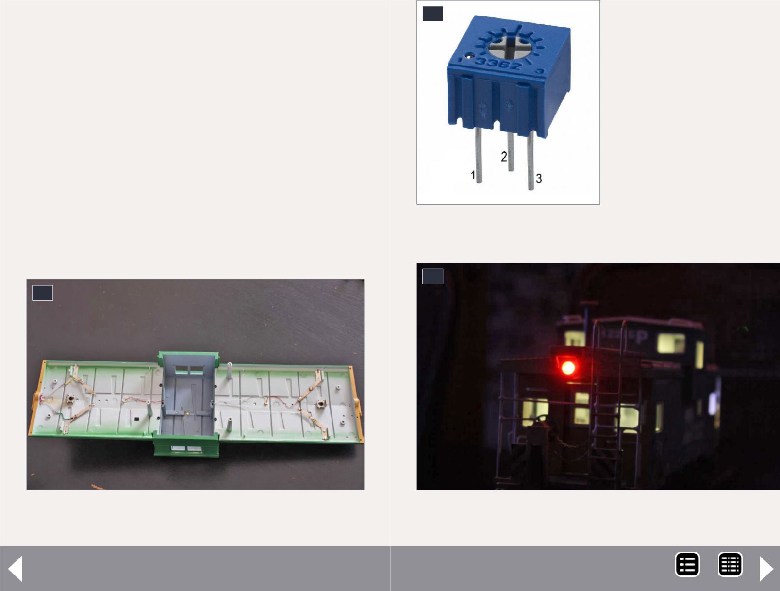
22. Pins 1 and 2 adjust
the resistance level
when the potentiometer
is turned. Pin 3 was
clipped off to avoid
confusion while wiring.
23. The EOT LED
22
23
MRH-Nov 2014


