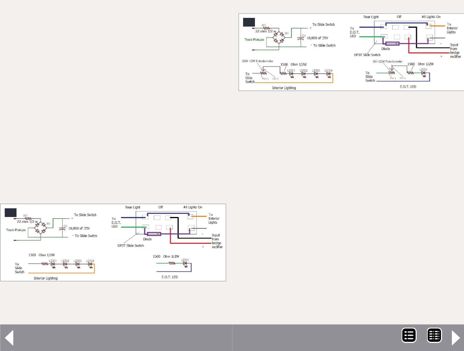
constant lighting from track power, while[18] adds a potenti-
ometer to adjust the light brightness.
I started by connecting the right-hand pickups from both trucks
together, as well as the left-hand pickups. [19] shows metal tabs
in the center of the floor at each end. These bring the truck
pickup wires and the interior wiring together. These pieces
do not move, and so I soldered them together for a better
connection.
I cut a piece of electronic breadboard from Radio Shack small
enough to fit into the 9-volt battery compartment [19]. Wired
to this board are the bridge rectifier and resistor R1. The AC
power is wired with green wires, and the DC power is wired
with red and white wires. Next to the metal tabs of the 9V bat-
tery compartment, the manufacturer stamped positive and
negative symbols on the floor. To keep things simple, I wired
the positive and negative leads from the bridge rectifier to
those respective metal tabs. From there, the positive and nega-
tive wires run to their respective places on the slide switch;
17. This is how I wired the lighting and the DP3T slide
switch. The lights are fairly bright, but not as bright as
the manufacturer’s lights.
17
Extended-vision caboose - 8
see [17] and [18]. The capacitor is also wired to the same tabs
on the slide switch as the positive/negative power inputs. I
wanted a capacitor large enough to keep the LEDs from flicker-
ing due to dirty track. I put in a 10,000 µF 35v capacitor. Some
say this is fine, others say overkill. For me, it’s doing the job I
want it to do. Running over semi-dirty track has resulted in no
flickering. From what I’ve read, 2,200 µF through 10,000 µF
will keep lights from flickering, but it all depends on how much
interior space you have to work with.
Electrical power is carried to the roof by metal tabs that run up
the side in each corner. I soldered a negative wire to one tab at
each end, and did the same thing for the positive wire. If you
look at the upper-left corner of [19] you’ll see the conductor’s
table I added. I used an N scale building door light as a desk
lamp. It seemed to be the right size at first, but now I’m won-
dering if an HO scale lamp would have been better. [20] shows
the conductor’s desk before being glued into place.
18. Here I added in potentiometers to control the
brightness for the interior lights and the EOT light. The
resistors near the LEDs prevent damage to them if the
potentiometer is turned all the way down.
18
MRH-Nov 2014


