Battery-powered models - 21
46
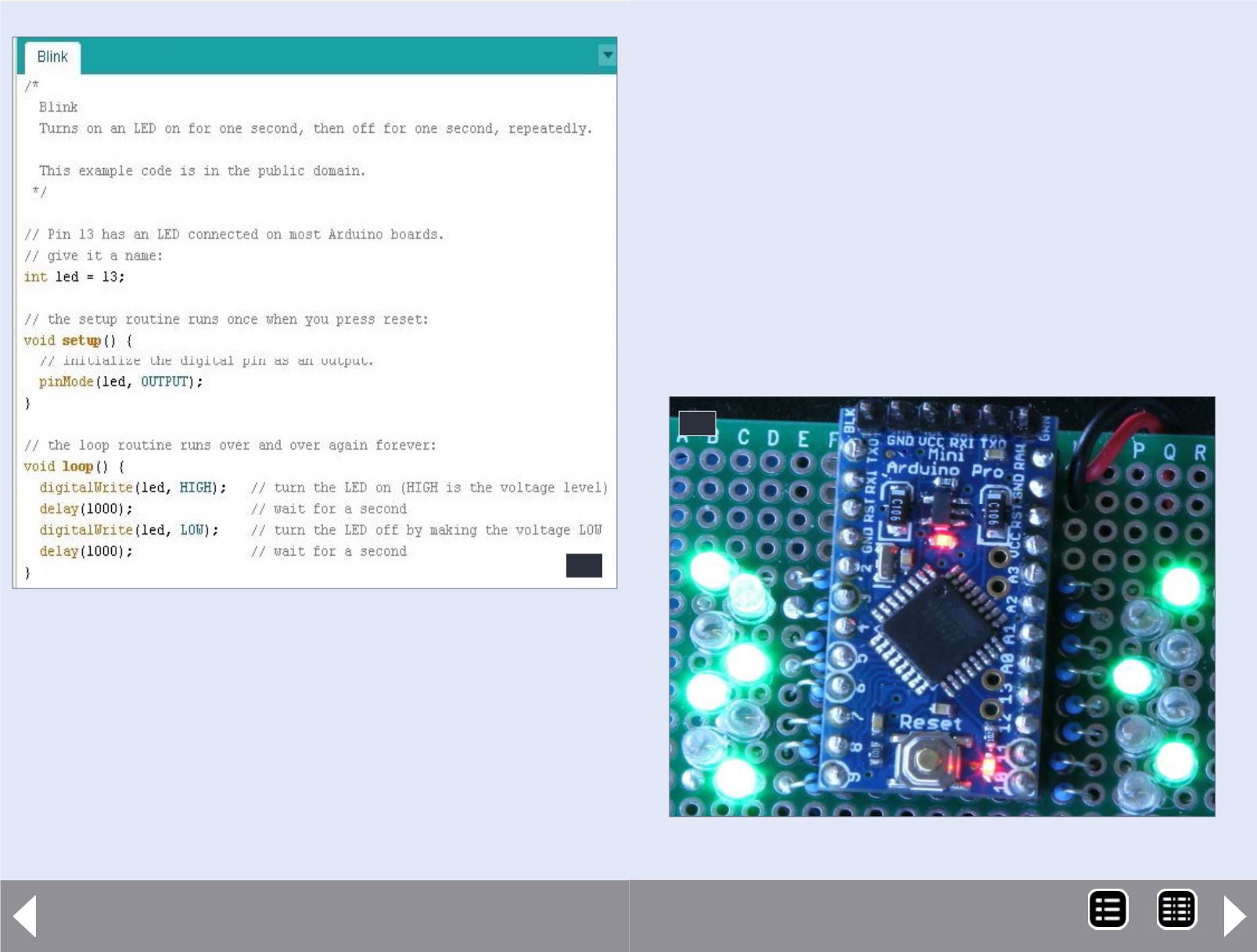
46. Simple LED blinking program
Connect a LED in series with a 1000 to 3000 ohm resistor. Typically
the longer length LED wire is the positive side. Touch the resistor/
LED combination to the exposed power adapter wires.
When the LED lights, you knowwhich of the wires is positive and
which is negative. Connect the Negative wire to GND on the pro
Mini and the Positive wire to the hole on the Pro Mini marked
VCC. Note this works for the Pro Mini mentioned before. There
are other variations for which this will NOT work. Only use a 5 volt
47. Building lighting demo board.
47
DC adapter here, rated 400 milliamps or more. Place your LEDs in
building rooms or where ever you want them, connecting all LED
anodes (Plus or positive sides) together and to the positive side of
your power source, in my case the 5 volt wall wart.
For each LED connect a 1/8-1/4 watt resistor of somewhere
between 330 and 2000 ohms depending on your LED and the LED
brightness you desire (experiment a little here) to the LED cathode
(Negative side). The other side of the resistor connects to one of
the Arduino pins labeled 2-13 and A0-A3 on the Pro Mini Board.
These are referred to as Arduino Digital Pins 2-17.
The assembly pictured below is my demo of this very project. The
LEDs will come on randomly, and, on the average, stay on for 60%
of the time. On the next page is a video demoing the final result.
MRH-Nov 2014


