to the motor, similar to a DCC
decoder’s speed control.
If left idle for many days the
battery will drain down. The
battery manager board will
isolate the battery from fur-
ther discharge to protect it.
The DC-DC converter needs
to be isolated from its load to
reset its operation. So a mag-
netic reed switch is used to
remove the load when not in
use, and limit battery drain.
Headlights
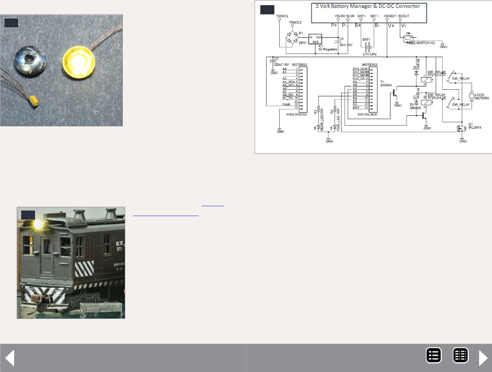
Working headlights are built by gluing sunny-white 0603 LEDs
onto the back of an MV Lens, with a 1/16” shallow hole barely
drilled into its center rear [24]. I use the pre-wired LEDs avail-
able from LedBaron
quite
a bit. For older models, I
like the effect it gives, with
a white LED with a yellow-
ish tint. I used to simply
glue the LED in the back of
the headlight housing, and
cover the front with a clear
styrene disk punched out
with a paper hole punch.
But I think the MV Lens
combination is an improve-
ment. Add some clear glue
26. 0603 White LED & MV
lens with rear hole.
26
27. Loco with “magnet box.”
27
Battery-powered models - 11
to cover where the wires attach to the LED back too, to insulate
the wire contacts and strengthen the connections.
All components are mounted on a piece of perf board run-
ning the length of the body shell and screwed to the top of the
chassis. The reed switch is mounted at the highest point, in
the middle and just under the roof. I use a small magnet glued
into a box-like structure, painted the same color as the body, to
make an unobtrusive on/off switch [25]. These reed switches
have worked out so well that I have ordered more to use in
future models.
Remote control
A model loco providing its own power will no longer respond
to voltage changes on the rails (DC) or to power and signal on
the rails (DCC). In fact, battery operation is by definition (at
28. Locomotive battery power block diagram.
28
MRH-Nov 2014


