Build your first resin car - 6
least it is there and not interfering with operation. Add all of
the brake piping according to the diagrams in the kit. The brake
levers have to be supported by brackets made with grab irons.
TIP:
Before drilling the holes, cut one of the grab iron legs off
a bit shorter than the other, but long enough to insert. Drill
a hole for one side of the grab and then see where the other
end falls. Mark this position with a pin or needle and drill. This
procedure gets the distance right every time. Thanks to fel-
low freight car modeler Clark Propst for this tip. He has used it
on a number of occasions to add car pulling eyes to the sides
of freight cars. The idea works just as well for grab irons and
loops. The completed underframe with the brake assembly is
shown in [10].
Sides and ends
With the underframe done, it is time to start on the ends and
sides. First, add the grab irons to both ends. To help with drill-
ing the holes, I mark the location with a pin to act as a center-
ing point, stopping the bit from wandering and spoiling the
part. Again, cut one side of the grab iron short and drill one
hole, then line it up with the nut-bolt-washer (NBW) casting on
the other side.
If it fits, go ahead and drill and mount the grab iron. If it
doesn’t fit, you will have to shorten or lengthen the existing
grab iron, or make another from wire. Once drilled, insert the
grab irons and attach them with CA from behind. After the
glue sets, nip off the protruding ends. In [12] you can see both
ends with the grabs. I use the .020” styrene spacer to set the
grab irons the right distance from the end and sides of the car.
Finish the ends with the ladders, trim them to fit, and add the
brake details to the B end.
10
10. Chain attached to brake line.
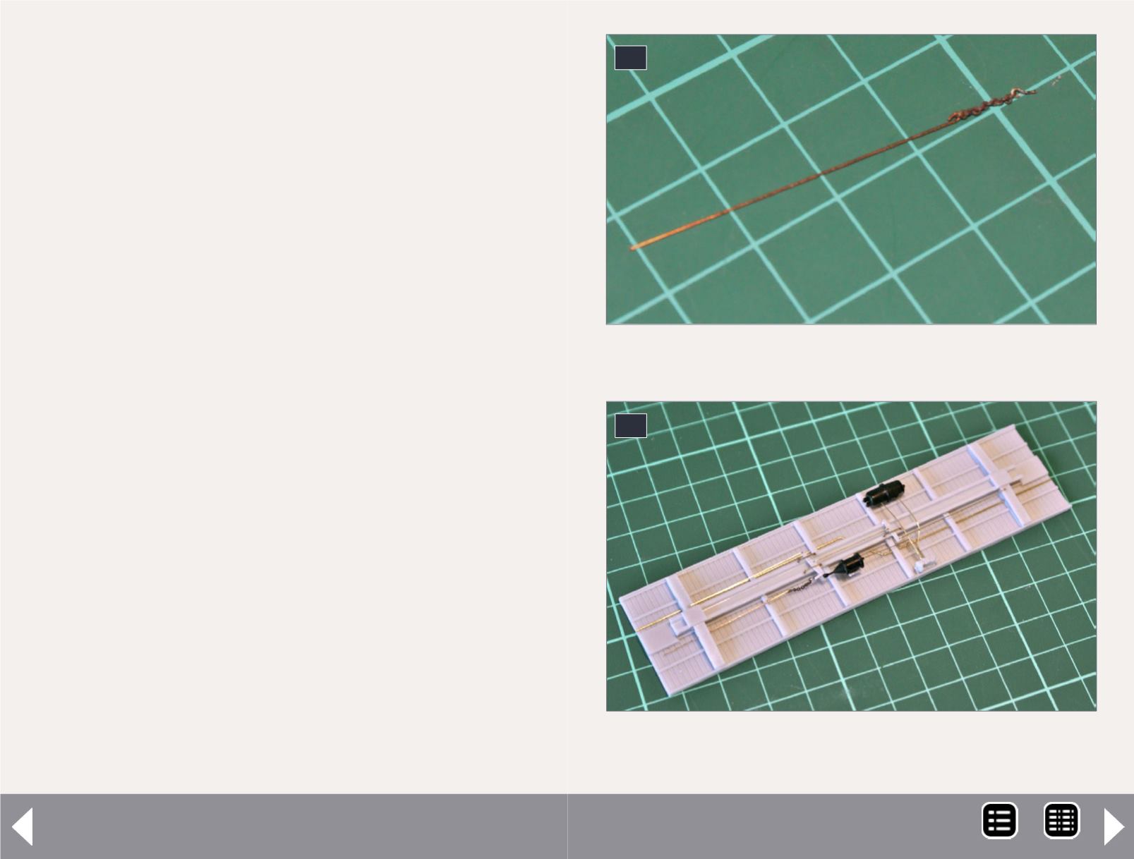
11
11. The brake valve, reservoir and brake cylinder with
piping installed.
MRH-Aug 2014


