Installing a sound decoder - 8
of insulation, twist the strands between your fingers so they
stay in line, and fold the exposed copper wire in half and into
a hook; do the same to the other wire. Don’t forget to slide a
3/8” to ½” length of shrink tubing onto the wire a few inches,
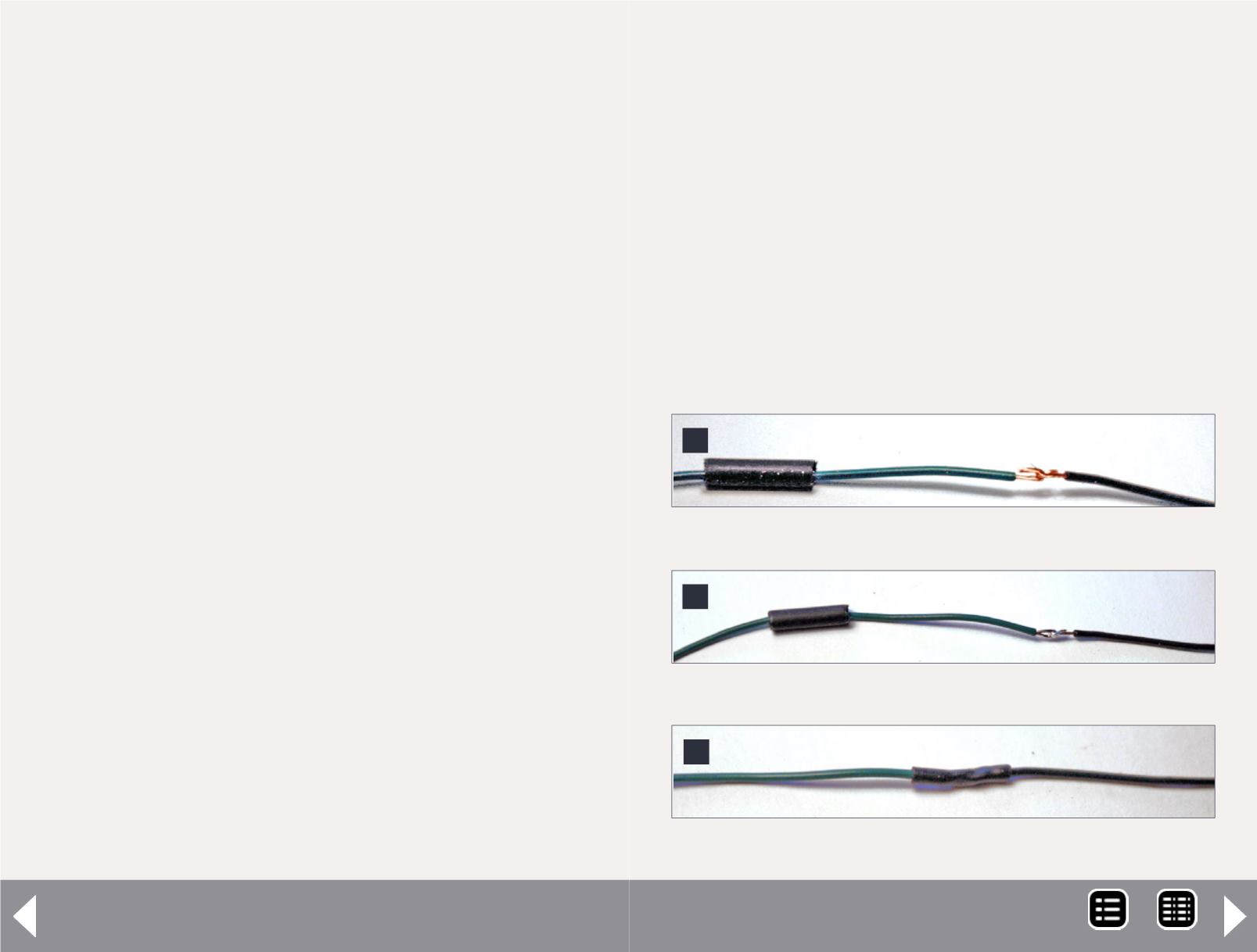
and you are ready to make a connection.
Hook the two wires together and pinch the ends so they’re
smooth with no strands sticking out (5). Now, while keeping a
slight tension on the wires in a straight line, hold the hot iron
under the joint, press the solder against the wires, and the
instant it melts, get away – you’re done (6).
Tests have shown that .005” of solder is enough to make a solid
electrical connection, so you don’t need very much; a typical
joint shouldn’t take more than two seconds. Do it quickly-- the
longer you heat up the joint, the more insulation you will melt!
Then slide the shrink tubing over the joint, be sure it covers the
bare wires completely, and hold the iron under it till it shrinks
tight (7).
When splicing-in a dropping resistor, cut the resistor leads
off to about 3/8” long and also bend them into a hook; use a
slightly longer piece of shrink tubing so it covers the leads com-
pletely. If you need to splice two resistors together, use a short
piece of ¼” shrink tubing that will fit over them and slide it
onto the joint between the resistors after they have been sol-
dered together.
When soldering wires to the motor, tin the end of the wire to
make a faster joint and deliver less heat into the motor.
Since the wires on the decoder will probably be much longer
than needed, it is time to plan where they will be routed so
you can determine the length of each one. You should have
3 or 4 inches of slack in the wires running from the boiler to
the frame, so you can remove the boiler without stretching
7: Finished splice.
7
6: Soldered splice, ready for shrink tubing.
6
5: Wires hooked together for soldering.
5
or breaking them. If you are not using Function 5 or 6, cut the
green and brown wires off at 2 or 3 inches and tape them back
onto the decoder along with any other unused wires and the
capacitor.
Assuming the decoder will be placed in the engine, it is impera-
tive that all wires be routed away from the motor shaft, flex
coupling, and any rotating parts. To make things easier, wire
the headlight and its dropping resistor, plus the wires to the
tender cable, and the wires and dropping resistor for the fire-
box LED, to the decoder on the bench beforehand.
Then the decoder and these wires and components can be
inserted into the boiler as a unit, avoiding a lot of splicing in
close quarters inside the boiler. (You can put the dropping
MRH-Dec 2013


