Installing a sound decoder - 4
cable that works very well. If this engine does not have a backup
light, you will only need a two-wire cable for the speaker.
The main criteria is this – there must be large enough open-
ings in the engine and tender so the cable is free to flex
without binding or limiting engine and tender movement on
curves and uneven track.
Since the engine is normally heavier than the tender, any
binds will usually show up on curves by the tender tilting
over, making poor contact with the track, derailing, or all
three. It is crucial that the hole in the tender front bulkhead
and the opening in the engine be the same height off the
rails; they must also be on the longitudinal centerline of the
engine and tender.
Take some time to measure and mark the locations accurately
so the holes line up vertically. Then remove the tender shell
and inspect it to be sure there is room inside to route the cable
past any bulkheads,
partitions or braces
and that there is room
on the frame/floor for
a speaker.
Any tender weights
may need to be
removed until this
portion is finished,
and reinstalled later
in a different spot. If
these items look good,
you can proceed with
making the cable
opening in the tender.
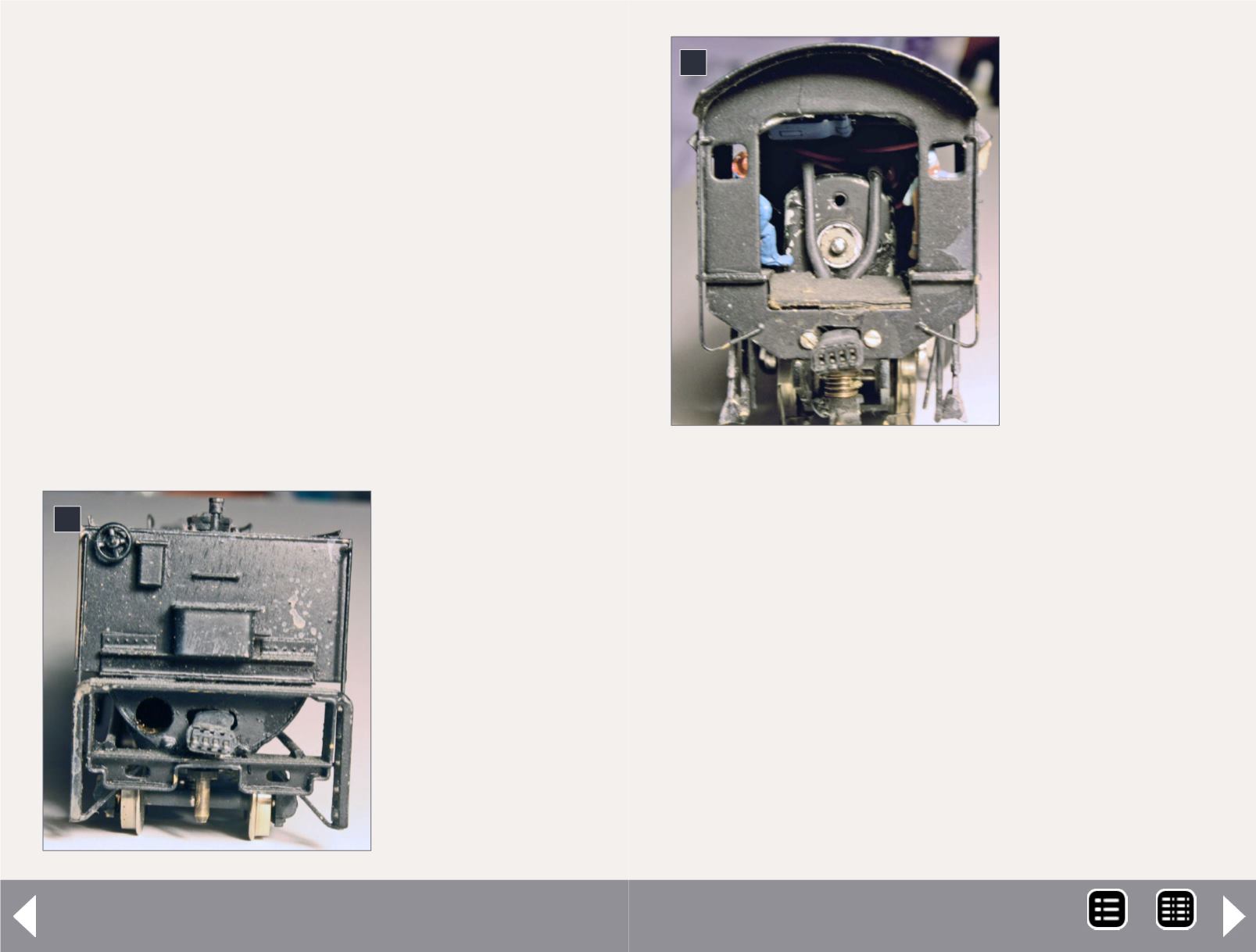
Figures 1 and 2 show
examples of the holes
cut for a four-pin
cable.
To make the opening,
I drill two or three
small 1/16” holes
first and then enlarge
them into one big
hole with a Dremel Moto-tool using a #113 engraving bit;
final shaping and smoothing is done with small files.
You must file the opening smooth with rounded edges so
they cannot snag or cut into the cable! I normally cut/drill the
four-pin Miniatronics cable opening at least 5/8” to ¾” wide
and about 1/4” high for the cable to feed through.
The TCS six-wire cable has much smaller wire so it is more flex-
ible and will not need as large an opening. With some engines,
there is plenty of open space under the cab, and running the
cable will be a simple matter, but others will require a hole in
the cab apron or even the frame. (While maybe easier, it looks
tacky for cables to be run on top of the cab and tender floor.)
Test-fit the cable with the engine and tender coupled, the cable
ends plugged together, and inserted into the holes you made. To
verify that the holes are large enough, you must be able to move
the tender up, down and sideways 1/2” independently of the
1: Front of tender
showing cable
cutout and cable.
2: Cable cutout
in cab apron and
cable.
1
2
MRH-Dec 2013


