marker LEDs are powered similarly. This is very straightforward.
The components are soldered to a scrap piece of perforated
circuit board, mounted to the caboose floor with double-
sided foam tape. No attempt was made to reduce the overall
size. Many variations were tried. The components are such
that all should fit with little effort, even in a four-wheel bob-
ber caboose. I used Kadee trucks with Intermountain metal
wheelsets, and added .08” phosphor bronze pickup wire pairs
to each truck. Track power was fed with very flexible 30 gauge
wire through the floor to the bridge rectifier. The regulator lim-
its the track voltage to the battery manager to 5 volts, when
power is available from the track.
The caboose marker lights are Utah Pacific marker housings
painted black. The lenses are created with Micro Kristal Klear
from Microscale. Once dry, they are colored with Tamiya clear
paint. The markers are lighted with a 0603 surface mount
(SMD) LED with 38 gauge wire leads. Working with such small
LEDs was covered in the February 2012 MRH article “Points
of Light”
Once you get used to it, it’s easy
and satisfying. When I don’t want the lights on, I position mag-
netic Mike on the caboose deck near the hidden, internal
11. Regulator comparison (left to right): PSU2-5,
78ST105HC, LM7805.
11
Battery-powered models - 6
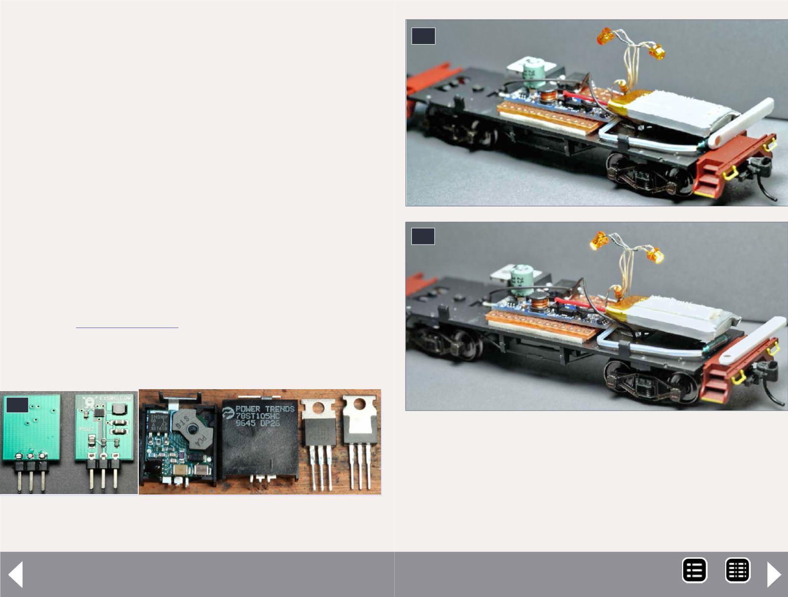
12
12-13. Caboose power unit w/reed switching via
magnet wand. 12 is off, 13 is on.
13
reed switch to shut things down. The battery will still charge
if there is power on the rails, until it reaches the charge limit
and stops. Simply remove Mike when you want the lights back
on. I have left Mike on board with a charged battery and come
MRH-Nov 2014


