the body. The motor trucks are disassembled. Cracked axles
should be replaced or repaired. Solder two thin, very flexible
wires to the side frame contacts directly (I replaced the ones
that came with the unit), and carefully solder two more directly
to the motor brush supports. Don’t melt the housing or you
may destroy the motor. This gives us independent pickups and
isolated motor contacts for independent control. I covered the
leveled top of the metal chassis with Kapton tape to prevent
any possible electrical shorts.
The block diagram outlines the power and control scheme.
In the first model, everything is powered with 5 volts from
the basic power block, exactly the same as the caboose light-
ing application. Even if you’re used to working with electron-
ics, battery power adds more constraints to design. I started
using the same H-Bridge devices I had used before (like the
SN754410 driver and the L298 device). But with only 5 volts
19. Original boxcab shell on right before bottom tabs
are removed.
19
Battery-powered models - 9
available they did not
provide enough voltage
swing out to the nomi-
nally 12-volt motors.
As an aside, I did con-
sider re-motoring with
6-volt motors but found
success before I had
to resort to this. I am
now considering using
a 6-volt or even a 3-volt
motor in the original
Roundhouse Boxcab
mechanism, even with
its poor power trans-
mission. The H-Bridge
designs usually solve
the problem of using a
single voltage source to
power a DC motor both
forward and reverse. I
even tried using a dis-
crete FET H-Bridge with
poor results. Success
came via a throwback! I
used an electromechan-
ical relay as a double-pole double-throw switch, just like DC
power packs typically use. The problem was the typical relay
would constantly draw power in its activated state, decreas-
ing battery life.
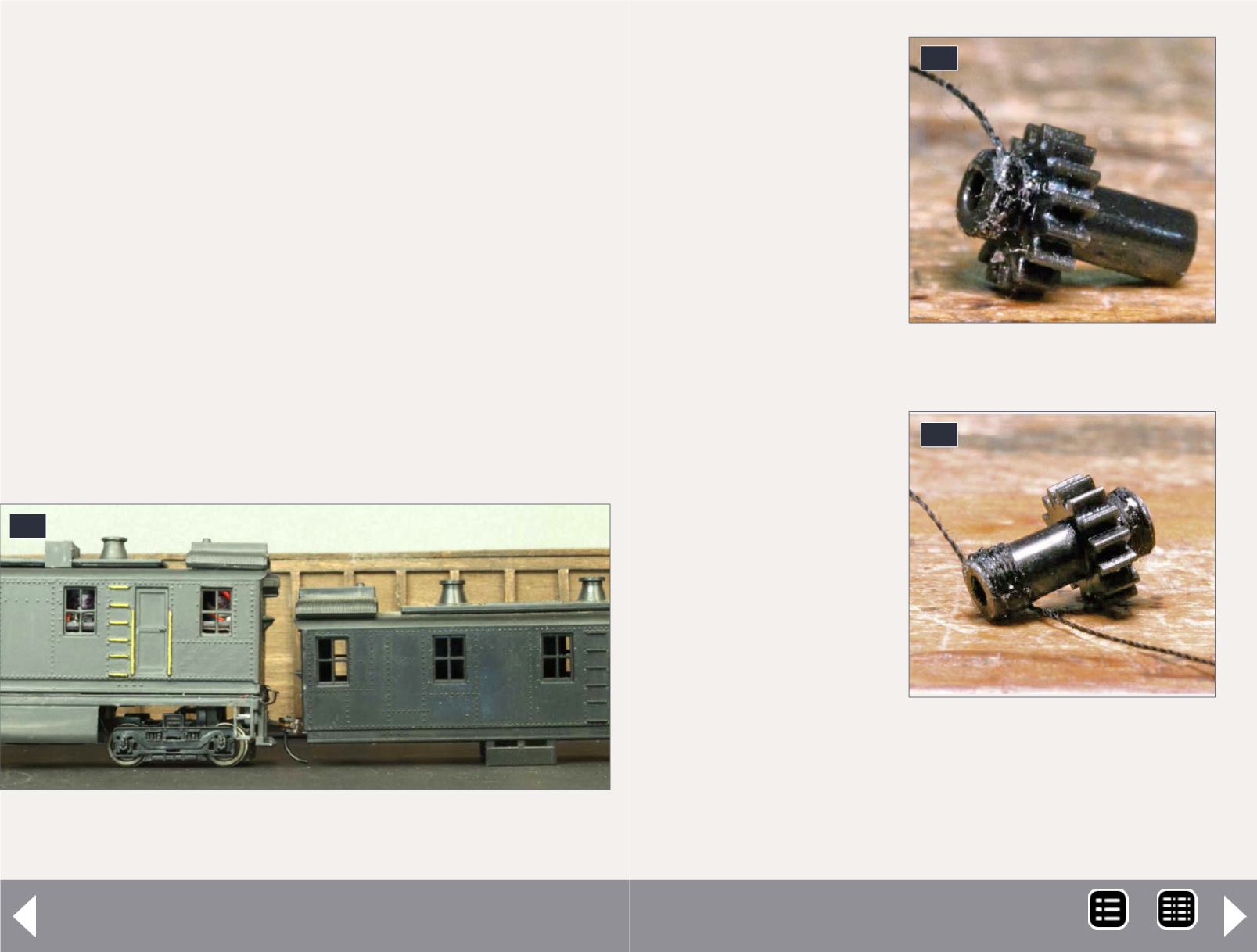
20. Repairing gears.
20
21
21. Wrapping the axle.
MRH-Nov 2014


