The solution was to use a tiny
latching relay which only needed
a short pulse to switch the con-
tacts. Look for 4.5-volt dual coil
latching relays at Digikey.com
or Mouser.com. The relay holds
its position until pulsed to the
opposite position. To maximize
the voltage swing to the motor,
a single, logic level FET transistor
was used to pulse (Pulse Width
Modulation - PWM) the power
22. Repaired gears back in the power truck. Note the
new motor wiring.
23. Loco1 boards mounted atop the 44-ton chassis. Note
that the left power truck has had its motor removed.
20
23
Battery-powered models - 10
24
24. Loco1 with 78ST105HC regulator mounted.
25
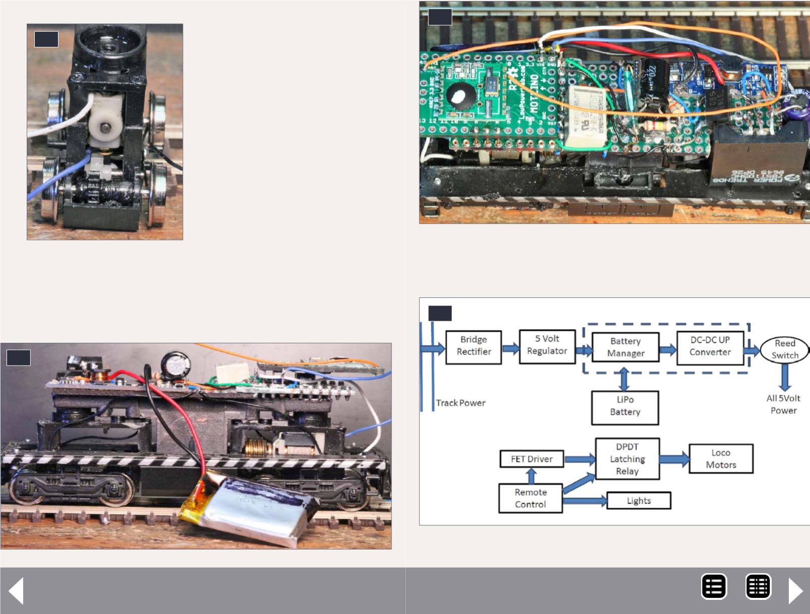
25. Locomotive battery power block diagram.
MRH-Nov 2014


