red, yellow, and green colored lens at the top of the sema-
phore blades. I programmed the Dual 3-Way to move the
semaphore blades so that the correct colored lens was illumi-
nated for each of the three aspects.
With the HiTech HS55 servos I used this worked fairly well.
If you're using really cheap servos, the positioning may not
repeat with precision.
Control Panel wiring
One of my goals is to have a semaphore control panel
present at each operator's desk. The Dual 3-Way can be
Up the Creek Column - 8
16
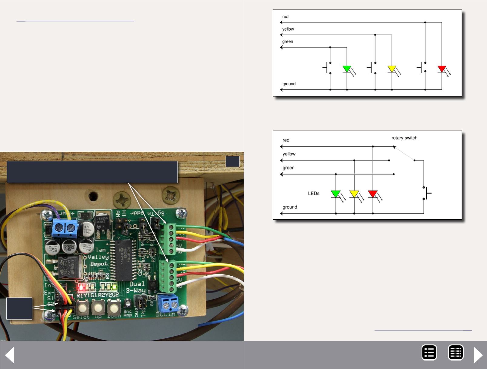
16: The Dual 3-Way controller installed and powered up.
Each of the two servo channels are controlled by
five wires: green, yellow, red, +5V, and ground.
Servo
wires
operated either by DCC addressing which is great for users
with JMRI Panel Pro or a hard-wired control panel. I didn't
want the extra expense and complication of adding a com-
puter screen for each operator so I chose hard-wired control
panels. The Dual 3-Way documentation includes a schematic
for a control panel interface that needs only four wires per
semaphore blade between the controller and a control
panel. That suited me fine.
17a: The three-button control panel schematic from Tam
Valley. Duplicate this circuit to control both semaphores.
17b: Panel updated for use with rotary switch and a
single push button switch. I tried this wiring at Oakhill.
MRH-Oct 2013


