Up the Creek Column - 5
Installing the servos
Installing the servo module – bracket and two servos – is primarily
a matter of getting things well aligned. The first things to position
are the semaphore blades – they should be at the yellow position,
about halfway between the low (green) and high (red) positions.
The next thing to align is the servo bracket. Position it so the two
semaphore control wires drop down between the two servos
and just behind the rear surface of the servo control arms (11).
Connecting the servos and semaphore
I removed the servo control arms from the servos and drilled
them with a #77 bit (.018") which was a couple thousandths
larger than the semaphore control wires. The control wires will
pass through these holes and slop needs to be minimized.
10
10: I mounted the sema-
phore by holding it in
place and tracing its out-
line with a sharp pen-
cil. With the semaphore
removed again I drilled
tiny pilot holes for Micro
Engineering small spikes.
I reinstalled the sema-
phore, double checked
its alignment and added
six spikes spaced around
its base. These appear to
hold it very securely.
The photo shows the
spikes before they were
driven home.
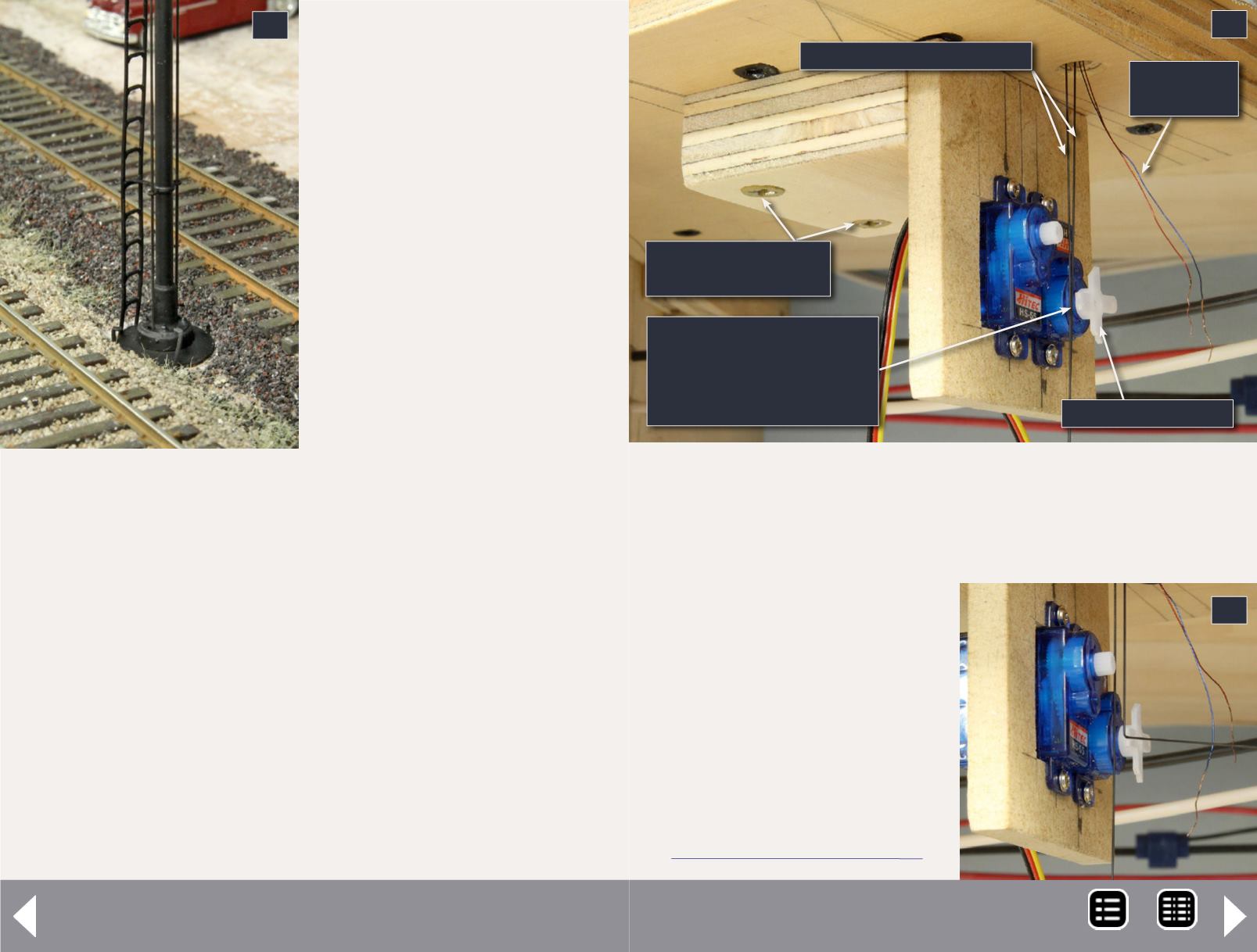
11: The servo module, aligned below the train order
semaphore and screwed in place.
12: A semaphore control wire bent to pass through a
servo control arm hole.
11
Servo module is located
such that the control
wires pass closely behind
the control arms.
Screws secure the
module to roadbed
LED power
leads
Semaphore control wires
Servo control arm
I fit the newly drilled servo
control arms back on the
servos and put a 90
o
bend in
the semaphore control wires
where they will pass through
the control arms (12).
The final step is threading
the semaphore control wires
through the servo control
12
MRH-Oct 2013


