Up the Creek Column - 4
Why TT&TO operation?
I bought a copy of the Opsig's (opsig.org) new book, "19 East,
Copy Three", and began refreshing my knowledge of running
trains on a dark railroad before reliable radio communications. It
turns out that co-author and former NP dispatcher Dave Sprau
lives less than an hour away from me! With trepidation I con-
tacted him and asked if he'd be interested in training the BC&SJ's
motley crew in the art of TT&TO operation. I was amazed – the
answer was yes! The BC&SJ was heading for TT&TO control.
I already had much of the paperwork (clearance cards, train order
forms, dispatcher log books, train sheets, and employee time ta-
ble) needed for TT&TO from a previous fling with it in 2005. Most
were usable or a few updates away from being usable. We had a
great training session with Dave and I scheduled the first regular
op session using TT&TO.
You may be wondering why I would abandon TWC (track war-
rants) which has been used on the BC&SJ since 2004. Track war-
rants were great, but for me there were three major issues:
The BC&SJ is set in 1952 and TWC wasn't feasible until around
1980 when radio communications worked everywhere.
My crews often spend a lot of time waiting for a hole in the ra-
dio chatter before they can call the dispatcher, and sometimes
the dispatcher is too busy to promptly dictate a new warrant.
Radios, especially those without headsets, create a lot of dis-
tracting noise in the train room. Often there aren't enough
radios to go around.
A crew using TT&TO makes their own decisions based on the time
table and their train orders and doesn't need direct contact with
the dispatcher. Of course, if things go wrong, the dispatcher may
need to write a flurry of train orders to fix things, but I hope that
will be the exception rather than the rule.
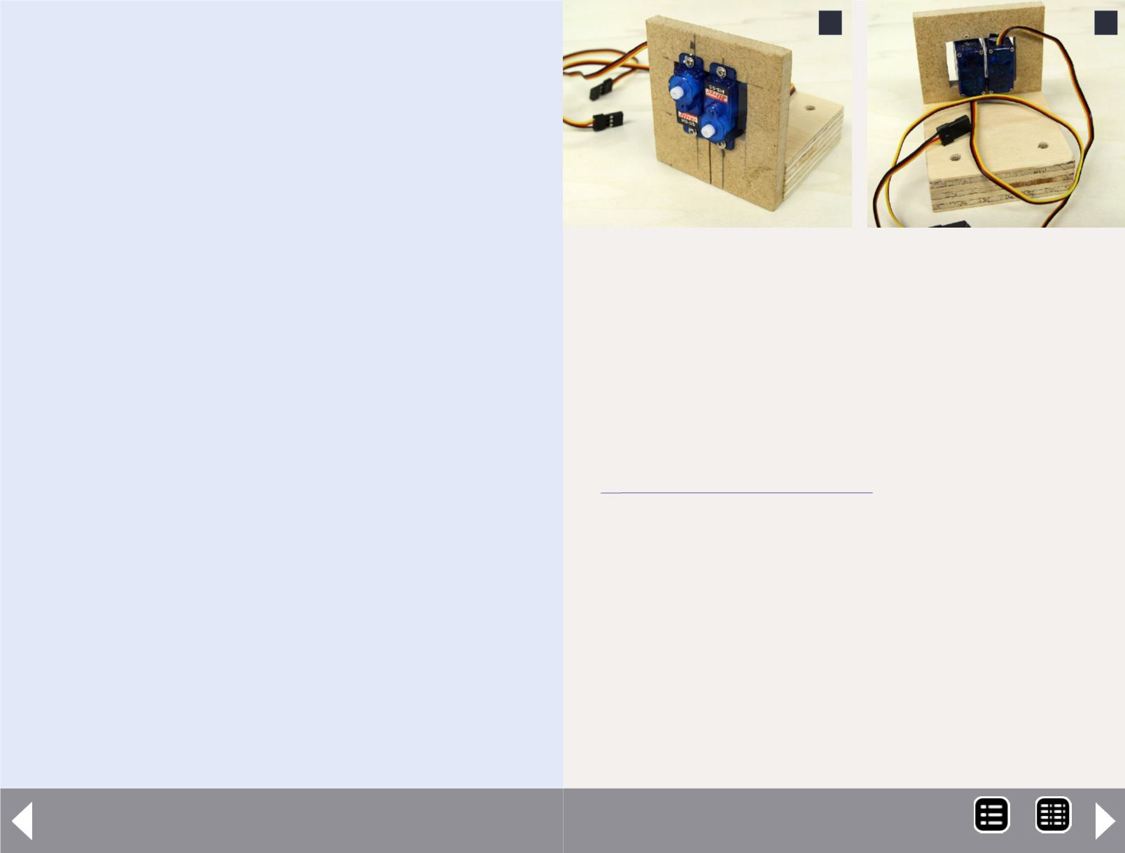
8 and 9: I made a bracket to hold the servos from scraps
of plywood and fiberboard. It's important that the servos
are held securely in place. If they move around it will
be impossible to make the semaphore blades operate
consistently.
Remember the 1/4" hole for the semaphore? The two
control wires are parallel but slightly less than 1/4"
apart. The servo pivot arms must be close to each other.
I staggered the servos to facilitate this while keeping
each pivot arm clear of the other.
I made an L-shaped bracket for the servos from scraps I had on
hand (8 and 9). The bracket needs to hold the servos securely
and provide a sturdy mounting point below the layout (note
the two mounting holes in the 3/4" plywood base).
Installing the semaphore
The Tomar instructions say to either glue or spike the sema-
phore in place pressing only on the base (to avoid damage to
the delicate ladder, blades, and mechanism). I chose to use
spikes so I'd be able to remove the semaphore if I screwed up
the mounting (10).
9
8
MRH-Oct 2013


