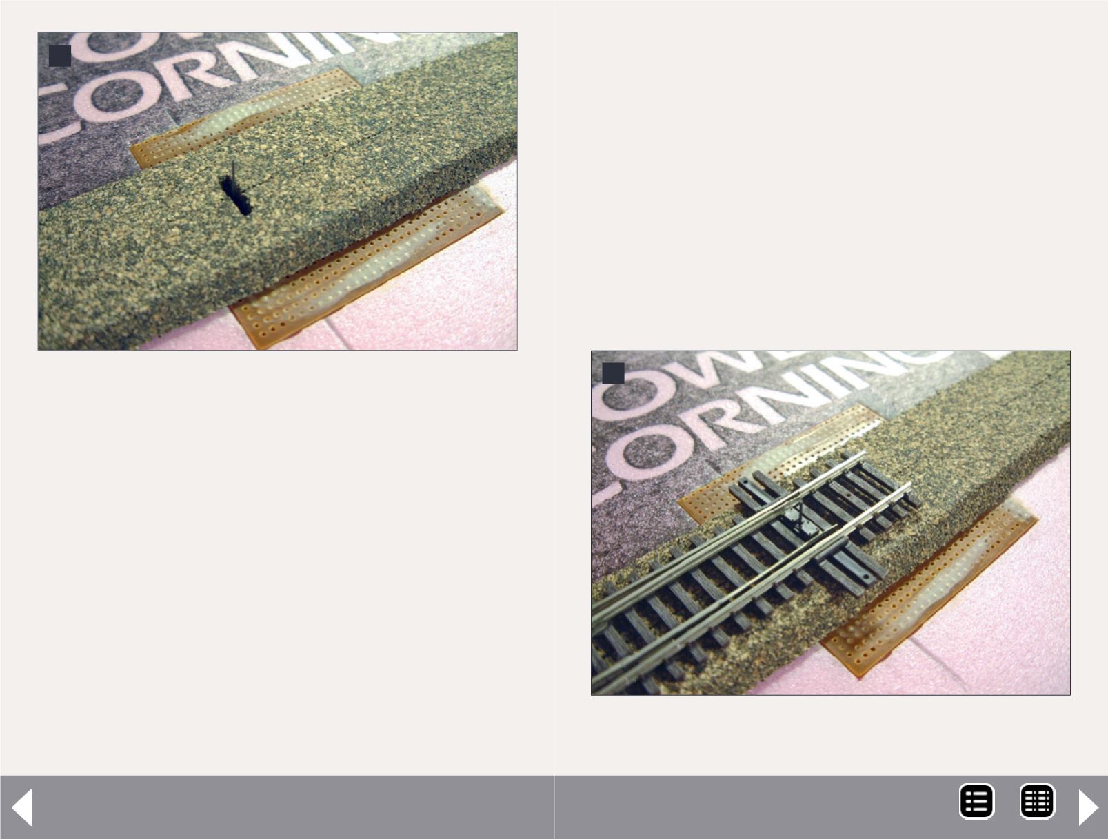
4: Glue is applied and switch machine installed. A slot
is cut into the cork roadbed for the actuator wire.
4
Switch machines on foam - 3
the foot of the rail. This was going to really simplify and speed
up turnout installation.
The entire turnout/PCB/Tortoise assembly could be done on
the bench ahead of time, making fine adjustment easier by
not having to work upside down. Mainline turnouts require a
bit more work. Prior to soldering the PCB ties to the feeders,
install the switch machine as depicted. Lay down and align the
cork next to the feeders and mark their locations. Drill them
out and glue down and trim your cork roadbed. After all is
installed and the glue cured, thread the feeders through the
PCB ties and install the turnout, finally soldering the feeders
as the last step. This method takes a lot of time. For some-
one with just a few turnouts, this might not be unreasonable.
5: Turnout is located, the actuator wired trimmed,
and ready to add track.
5
Flattening the tops of the feeders will make them look like
spikes, thus hiding them among the rest of the trackwork.
As we continued building with CVT turnouts and Proto:87 Stores
solderable heel-blocks, which had no PCB ties, we graduated
from using copper clad in favor of using perf and non-perf board
as depicted. The perf board worked really well with Liquid Nails
adhesive. The holes allowed the adhesive to really grab the
board and hold it into place. It took another step to hide the
holes, but the preference to having a solid bond between foam
and PCB was worth the extra step.
Using this method yields another nice benefit. The stock actua-
tor wire included with the Tortoise is sufficient to adequately
MRH-Nov 2013


