The location for cross-drilling is important. When the stand is
mounted on its shelf, and thrown half-way, the lever should
be parallel to the fascia. The best way to determine this is to
insert the extension into the shelf, mount the switch stand, and
determine where the hole needs to be. It may vary between
switch stands.
Mounting the switch stand
For each stand, cut a shelf 8”x 2-3/4” from ¾” pine board. The
shelf is deep enough to make using the switch stands com-
fortable. Sand the shelf to remove sharp edges and round the
aisle-side corners so they won’t catch on clothing. Drill a hole
to a press-fit for the brass collar, then space the two head
blocks to accommodate the mounting holes on the base of the
switch stand and glue them in place.
...make sure that there’s
some framing support for
each shelf.
Insert the brass extension tube from the bottom of the shelf
and bolt it to the bottom of the switch stand. Then mount the
switch stand to the head blocks with small screws.
To mount the completed assembly to the layout, I determine
where each control would go, making sure that there’s some
framing behind my layout’s Masonite fascia to support each
shelf. For each switch control, I locate and drill two holes in
the fascia for mounting screws, then use these holes to locate
and drill holes in the back of the shelf. 2½” screws will provide
plenty of support.
Realistic switch control - 5
Before securing the shelves in place, I note the location where
the control rod will pierce the fascia, then drill a hole in the
fascia, sized to create a press-fit for the rod’s outer sleeve. I
finish the installation by connecting the control rod between
the switch stand lever and the appropriate BullFrog. To make
this connection, I use appropriately sized Gold-N-Clevises from
Sullivan Products
, a supplier to the RC
aircraft hobby. I liked the clevises so much I used them at the
BullFrog end of the linkage, too.
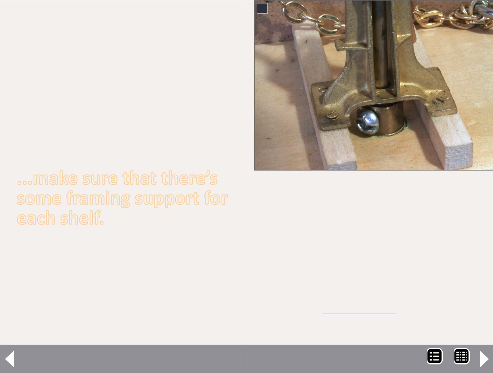
9
9. Here’s a closeup of the base of a modified switch
stand. It shows the two sizes of tubing used to make
the extension that transfers the movement to a lever
below the shelf. It also shows the screw that replaces
the threaded rod to secure the extension to the stock
switch stand.
MRH-Aug 2014


