7
7. At the other end of the plastic control rod, a
BullFrog manual switch machine moves the points.
The BullFrog has been fitted with a larger wooden face
to support the control rod, since the use of clevises
required moving the position of the rod.
Realistic switch control - 4
Cut the extension from 3/8” diameter brass tube. Length will
vary depending on the shelf used, but it needs to be long
enough to connect to the bottom of the stand and extend
about an inch below the shelf.
Cut a collar for this extension from 7/16” brass tube. The
length will be the same as the depth of the shelf. Clean up the
cut ends to make sure the 3/8” brass tube slides smoothly
through this collar.
Solder a 1” length of brass bar stock (see Bill of Materials) to
the bottom of the extension tube creating a lever. Drill a couple
of holes in the lever to provide some choices for connecting
the control rod.
The final step is to cross-drill the extension tube to secure it to
the bottom of the stand with a machine screw, so the exten-
sion will rotate when the stand is operated. The machine screw
replaces the threaded rod that comes with the switch stand, so
use the threaded rod to determine what size screw to use.
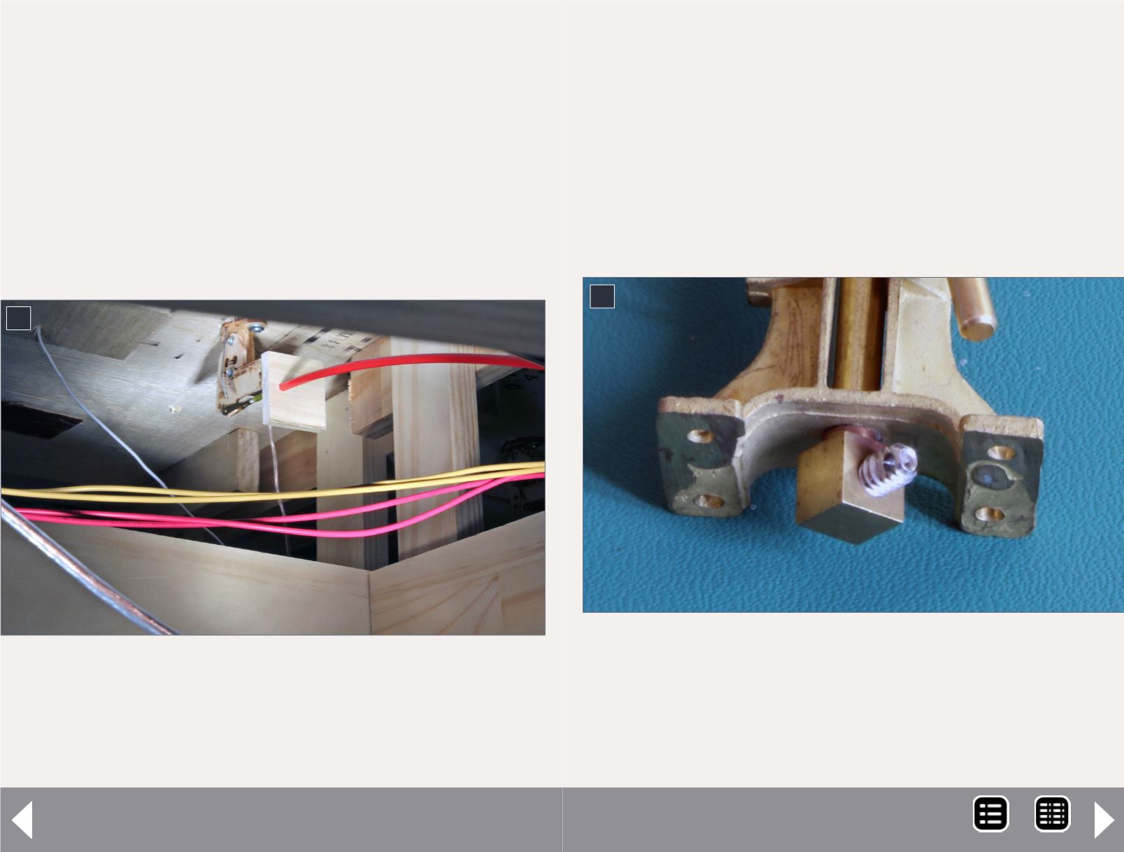
8. Here’s a closeup of the stock switch stand from
Sunset Valley Railroad. As designed. the brass cube at
the bottom of the stand is drilled to accept a threaded
rod. This will be replaced with a screw to secure a
brass tube to the cube and create the extension lever
required for use on the layout.
8
MRH-Aug 2014


