end of an S-shaped crank, made from 0.015 inch brass or steel
wire (3-4)..
To make construction, adjustment, and mounting easy, I
screwed a strip of black styrene onto a small wood block to
hold the assembly. Take the trimmed and shaped plastic fig-
ure, and cut its head off(!) using the thinnest saw blade you
can get. Otherwise a thick kerf will remove too much material.
The cut needs to be flat and level. I had to practice this a few
times before I got it right. Drill down from the center of the
neck through the torso with a #77 bit. This hole should exit the
bottom of the torso the same distance as the motor shaft cen-
ter to the outer can of the motor. Next, drill a #79 hole in the
center of the neck into the head. Then glue the torso onto the
top of the block-mounted plastic strip, which should protrude
above the wood just a tiny bit. I angled the torso so it would
“lean” towards the outside of the window (5-8).
Teach Your Engineers to Turn Heads - 2
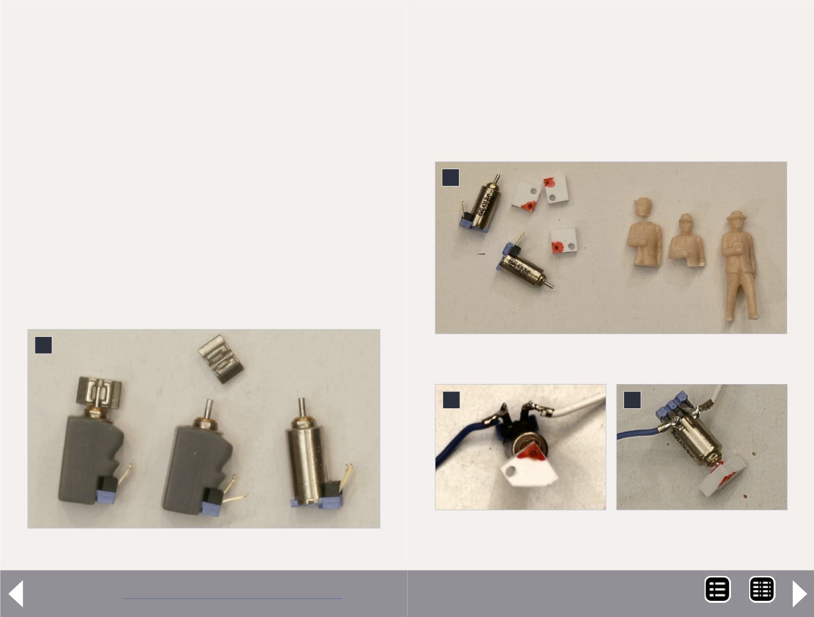
1: Original pager motor and weight removed.
1
2: Motor coupling pads and figure reshaping.
2
3
4
3: Motor and block top
view.
4: Motor and block side
view.
Now press fit the motor onto the styrene block you drilled
above. Shape and cut the S-shaped crank, and insert it into the
torso. Attach the motor onto the black strip with a small strip
of masking tape, inserting the crank as you do. Now make sure
your motor/block/crank alignment allows you to move the
crank in an approximately 90 degree turn effortlessly. The axis
of the crank shaft in the torso should align with the axis of the
MRH-Feb 2013


