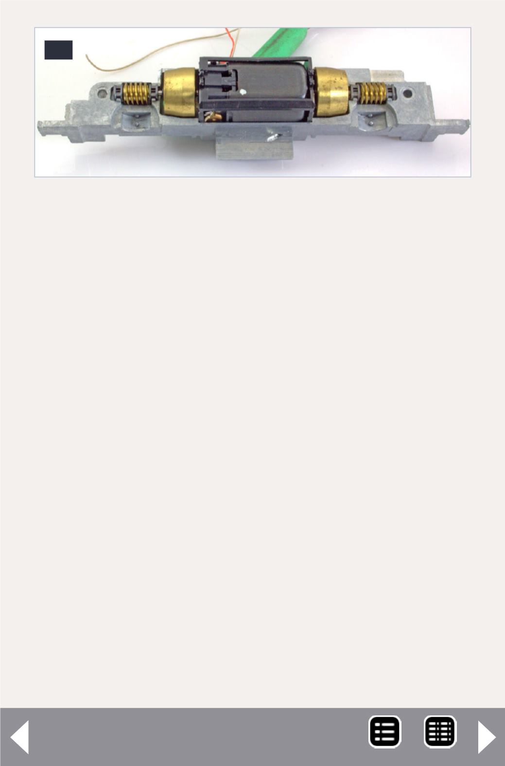
the worm gears, the adapter sleeves and the motor into the
left frame half, as shown in figure 19.
6.4 Position motor wires
The motor wires need to be routed out the top of the frame
in such a way that they won’t be cut by the frame. The wires
need to be positioned so that they won’t contact either frame
half. See figures 15, 19 and 20. If you have any questions, use a
piece of Kapton tape to prevent a short. The motor in figure 19
didn’t have any clearance issues. The one in 20 might, so I used
Kapton tape, just to be sure. After the photo (20) was taken,
the motor mounting clip was rotated around the motor shafts
until it was in the position shown in figure 19.
6.5 Assemble frame halves and trucks
The next step is to put the cleaned trucks into the left frame
half and put a drop of 10- weight Nano-Oil where the truck
slides on the frame.
6.6 Lightly tighten screws
Once you have the parts positioned as shown in figure 21,
slide the other frame half over the drive train and tighten the
19
19: Drive train reassembly ready for trucks and
insulators.
DCC Impulses column - 12
MRH-Jan 2013


