10.0 Install and wire decoder
Now, we get down to the fun part. You can see the locomotive
return to running condition. Figure 26 shows the locomotive at
the end of the work here in section 10.
10.1 Set decoder in position and secure
In the end, the decoder is not held in place by any mechanical
method. The sides of the frame will keep it in line (that’s why we
put Kapton tape on them). The wires will hold it front to back.
This installation is designed for the SoundTraxx TSU-GN1000
decoder (part number 678-828050 with the EMD 567 sound
file). The decoder needs to be installed with the FRONT letter-
ing toward the back of the loco and the power supply capaci-
tors in the well behind the headlight. Hold it temporarily in
place with a bit of blue tape, as shown in figure 26.
10.2 Wire motor
Cut the orange and gray wires to length and solder them to
the motor pads. If you observed polarity when removing the
25
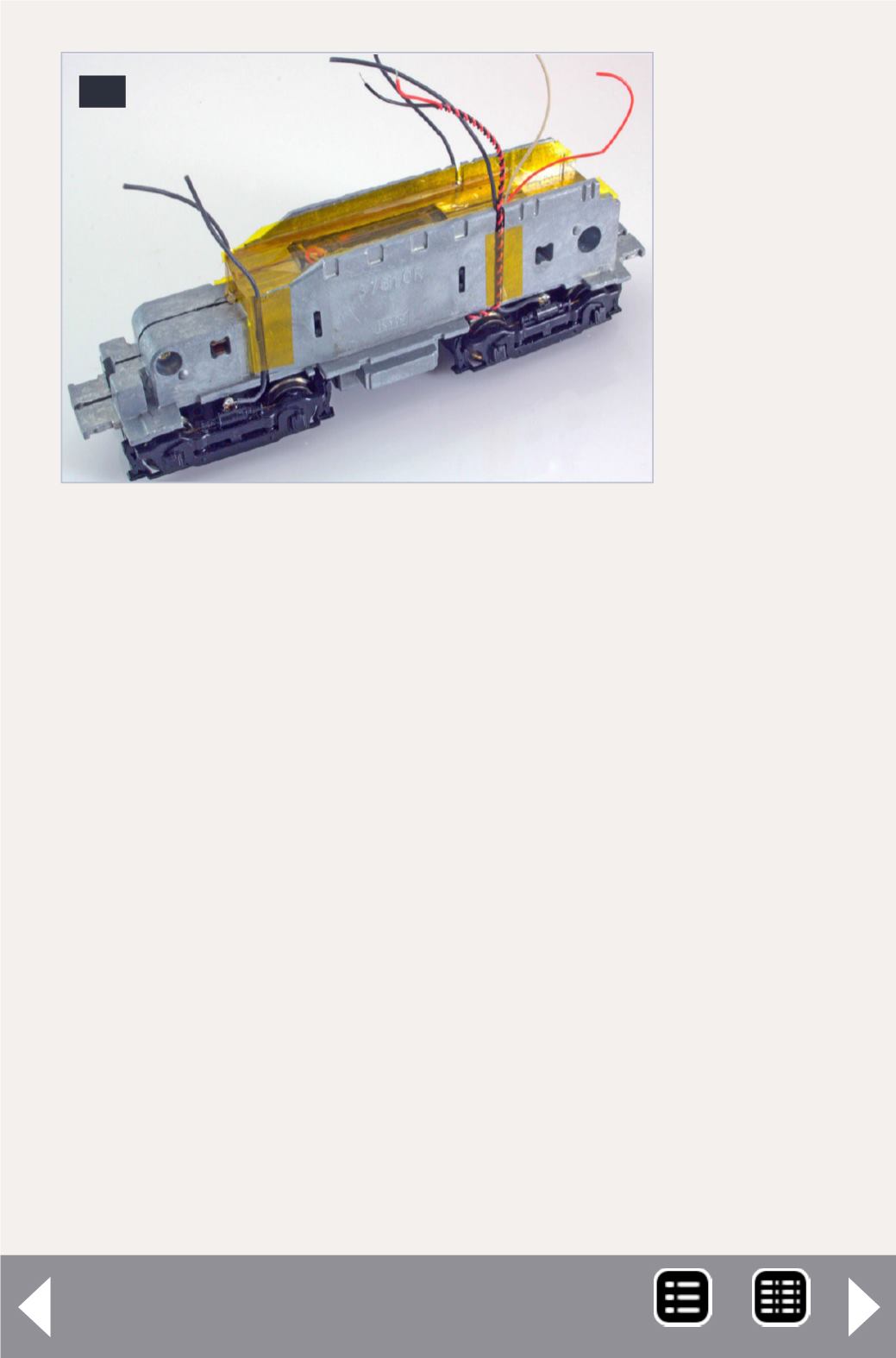
25: Top
view of
the trucks
wired,
after
Kapton
tape has
been
applied to
hold the
wires in
place.
DCC Impulses column - 15
MRH-Jan 2013


