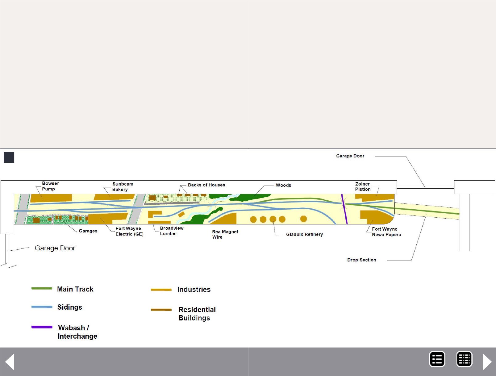
2: The Fort Wayne Union Railway track plan has 2 distinct
switching areas that are separated by a small creek. The area
to the right is strictly an industrial area, representing indus-
tries built during the WWII timeframe. The area to the left of
the creek represents a mix of industrial and residential struc-
tures, typically built between WWI and the Depression era.
4. The layout can fit along one side of a garage.
5. The layout can serve as a base for developing ones skills on
different aspects of modeling railroading.
I designed the layout to include an interchange with the
Wabash RR, since on the prototype it was the only one with
an overpass. On the prototype, the railroad ended at the
NKP main a little north of the Wabash and at the PRR yard
approximately 2 miles to the south.
I did not limit myself to the industries that are served by the line,
but rather used different industries that were a part of the Fort
Wayne industrial base beginning the 1940s. Motive power on this
Fort Wayne Union Railway - 2
2
Designing the layout
With this brief prototype history, I chose to proto-lance a small
switching layout as my entry into the MRH design challenge.
Given the limitations on money forces one to think about what
you should spend the funds on and what to ignore. I view this
layout as a section that can be further expanded in the future. I
have also made the assumptions:
1. The modeler has had some previous experience as a youth
building models or model railroading
2. The modeler has limited space available at the present time
3. The layout must be expandable in the future.
THE FORT WAYNE UNION RAILWAY Track Plan
MRH-Jan 2013


