3: These are the three sub-assemblies required to
make the bumper.
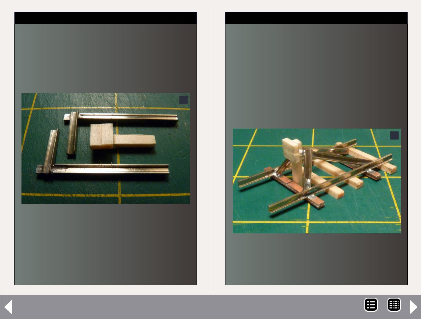
STEP 3:
I then assemble the components. I solder the 1-1/4" and
1/2" rail pieces at 90⁰ angles to each other, making mir-
ror pieces. I wire-brush any solder residue from the rails.
I glue (using fast setting CA) the two 1/4" wood tie pieces
next to each other to form 1/4" wide pad, two ties high.
When dry, I glue the pad to the top of the 5/8" wood tie
which becomes an upright support for the pad.
3
Scratchbuilding a Code 83 Rail Bumper - 3
4: This is the completed bumper ready for
installation.
STEP 4:
Now, I glue the bottom of the upright pad support to the
side of one PCB ties facing the middle of track section.
When the glue dries, I lean each 900 rail piece onto oppo-
site sides of the top of the upright pad support behind the
pad. The end of the 1/2" rail piece should rest on the PCB
tie and the end of 1-1/4" rail piece should drop between
the other PCB tie and the last wood tie. Make sure the
ends of the 900 rail pieces are touching the inside of stock
rails. Touch top of 90⁰ rail pieces with a drop of glue, and
wait to dry. Then solder the ends of the 90⁰ rail pieces to
inside of the stock rails
4
MRH-Jun 2013


