“Series” means wiring a
string of LEDs together
with the negative termi-
nal from one connected
to the positive terminal
of the next. I glued the
LEDs to the roof using
CA [21].
The EOT LED fit nicely
into the lens without any
kind of adhesive. The
EOT LED was wired like
any other single LED. As
seen in [17] and [18],
both LED circuits used a
1500 ohm ½W resistor. I
tried using a larger value
for the interior lighting circuit, but the LEDs were to dim for
me. I found there was a fine line between being too bright and
looking toy-like, and not being bright enough to see the inte-
rior detail.
So I used potentiometers [22] to adjust the brightness of the
LEDs. Use a multimeter in ohms mode to check which two pins
show the resistance value changing when the potentiometer
is turned. For the potentiometers I used, pins 1 and 2 were the
pins that showed the resistance changing. I clipped off pin 3 to
avoid any confusion while wiring.
For the interior lighting I used a 250K ohm ½ watt potentiom-
eter. For the EOT LED I used a 10K ohm ½ watt potentiometer.
The LED brightness can now be adjusted like your car dash-
board-from very dim to nice and bright.
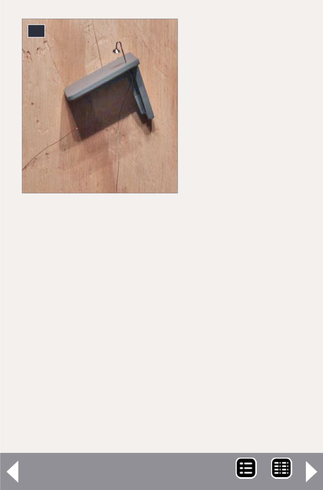
20. The conductor’s desk with
lamp.
20


