constant lighting from track power, while[18] adds a potenti-
ometer to adjust the light brightness.
I started by connecting the right-hand pickups from both trucks
together, as well as the left-hand pickups. [19] shows metal tabs
in the center of the floor at each end. These bring the truck
pickup wires and the interior wiring together. These pieces
do not move, and so I soldered them together for a better
connection.
I cut a piece of electronic breadboard from Radio Shack small
enough to fit into the 9-volt battery compartment [19]. Wired
to this board are the bridge rectifier and resistor R1. The AC
power is wired with green wires, and the DC power is wired
with red and white wires. Next to the metal tabs of the 9V bat-
tery compartment, the manufacturer stamped positive and
negative symbols on the floor. To keep things simple, I wired
the positive and negative leads from the bridge rectifier to
those respective metal tabs. From there, the positive and nega-
tive wires run to their respective places on the slide switch;
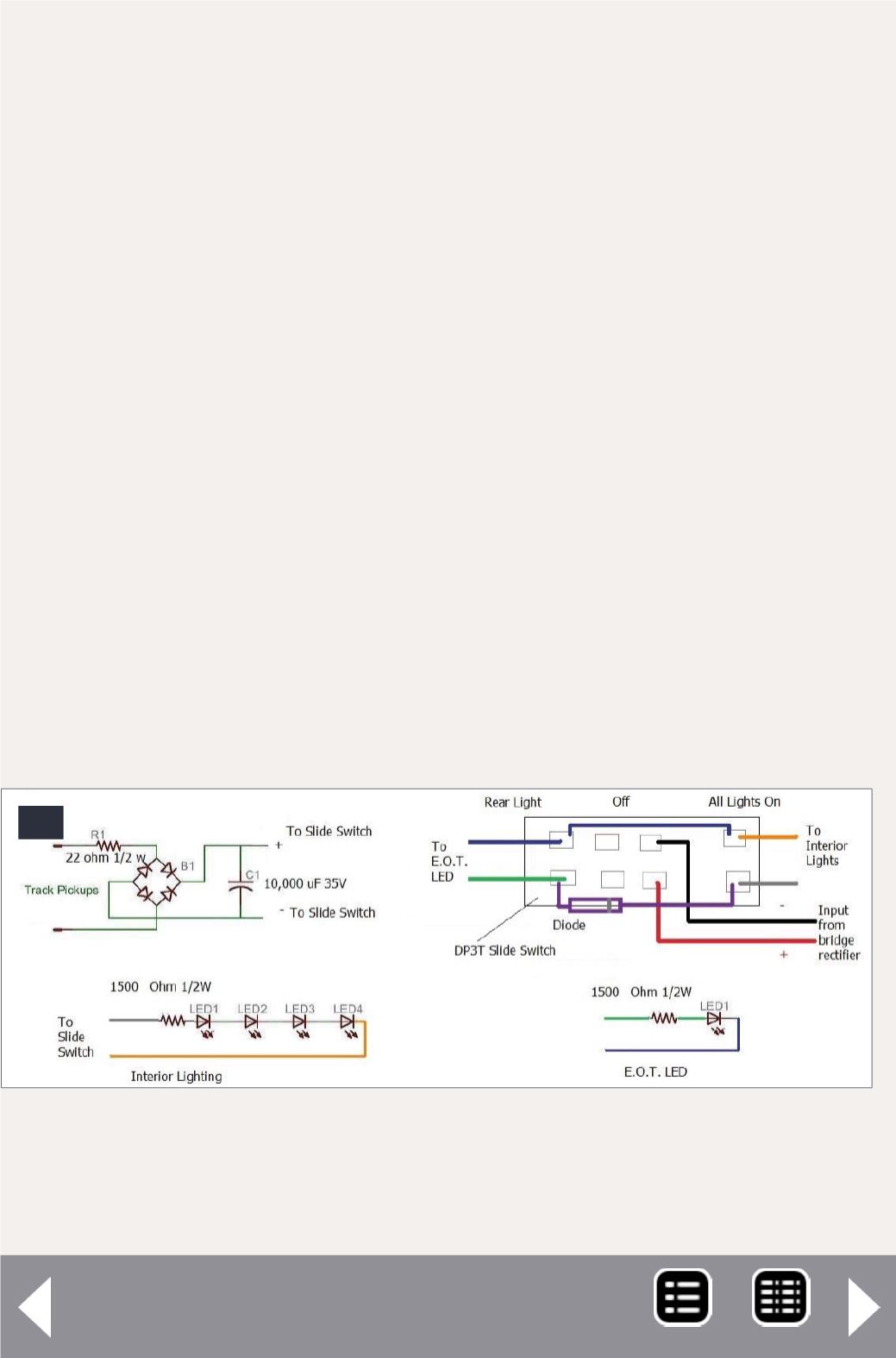
17. This is how I wired the lighting and the DP3T slide
switch. The lights are fairly bright, but not as bright as
the manufacturer’s lights.
17
Extended-vision caboose - 8
MRH-Nov 2014


