Activity recorder modification
Some hardware modifications and new software can turn the
original circuit into a digital train travel recording unit. To use
the controller this way adds two switches, a potentiometer
(abbreviated “pot”), a relay, an external memory IC, and a few
other simple parts.
Here is the board from part 1 without the recorder modifica-
tion. The highlighted areas were not used in the first project
but the additional parts outlined here make the recorder.
The extra components include:
Speed potentiometer - 50,000 ohms, linear taper (any
thing from 15K to 100K should work well)
SPST push button switch
SPST toggle switch
(optional) SPST push button switch to start each playback
session
Relay (either 5 volt or 12 volt - see text)
2N2222 NPN transistor
8-pin DIP socket
24LS256 memory IC (others will work for more recording
time - see text)
1K resistor
470 ohm resistor
two 4.7K resistors
LED
1N4001 diode (any generic silicon diode will work)
The photo at the top of the article [1] shows the completed
board with the blue 12-volt relay shown here. The black relay
next to it is a 5-volt unit that fits into a 16-pin IC socket.
Using the recorder
There are two modes of operation. In the RECORD mode the
potentiometer is used to adjust the speed and direction of
the train. When the pot is in the center position, the train is
stopped and the amber LED is lit. When the pot is rotated to
6
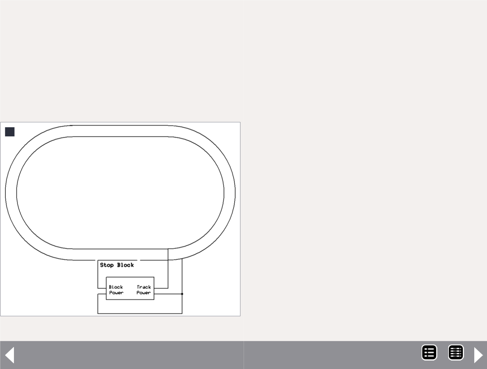
6. Track wiring using a stop block.
PICAXE circuit part 2 - 4
MRH-Jul 2014


