8
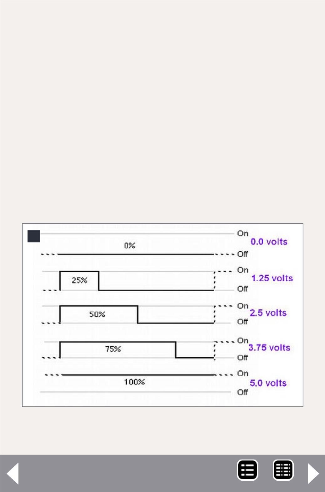
8. How the PICAXE pulse width modulation (PWM)
pulses simulate variable voltage.
PICAXE circuit - 7
All power control is performed by pins 6, 11, and 9 on the
PICAXE. These pins control the output of the L298N H-bridge.
The L298N is designed to operate two separate motors, each
drawing up to 2 amps. In this application we are controlling
only one motor, so its control and output pins have been wired
in parallel, to supply up to 3 amps of current to the motor.
When the PICAXE’s pin 6 is at +5V (known as “high”) and pin 11
is at 0V (known as “low”), the motor will rotate in one direc-
tion. When pin 6 is low and pin 11 is high, it rotates in the
opposite direction. LEDs D2 and D4 light to show you which
direction the L298N is set to.
MRH-Jun 2014


