8
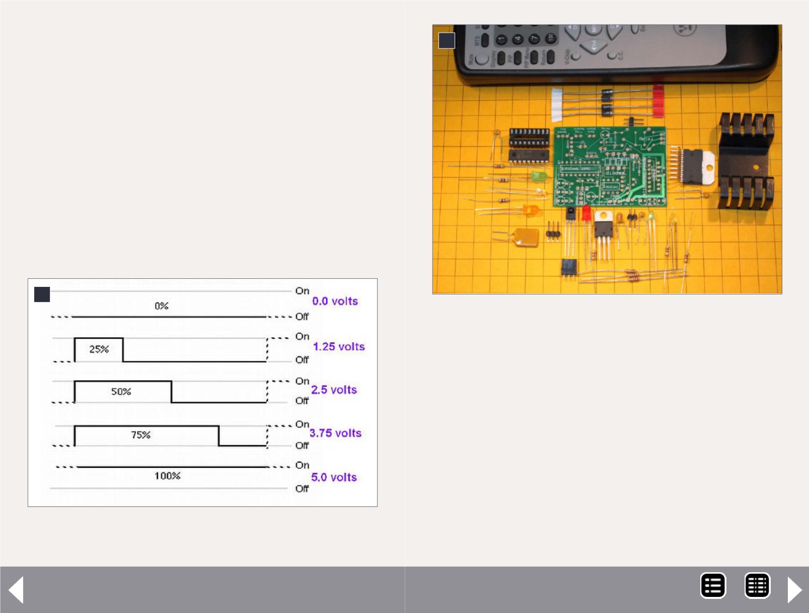
8. How the PICAXE pulse width modulation (PWM)
pulses simulate variable voltage.
PICAXE circuit - 7
All power control is performed by pins 6, 11, and 9 on the
PICAXE. These pins control the output of the L298N H-bridge.
The L298N is designed to operate two separate motors, each
drawing up to 2 amps. In this application we are controlling
only one motor, so its control and output pins have been wired
in parallel, to supply up to 3 amps of current to the motor.
When the PICAXE’s pin 6 is at +5V (known as “high”) and pin 11
is at 0V (known as “low”), the motor will rotate in one direc-
tion. When pin 6 is low and pin 11 is high, it rotates in the
opposite direction. LEDs D2 and D4 light to show you which
direction the L298N is set to.
The H-bridge spins the motor at full speed when it receives
+5V (“high”), and stops it when it received 0V (“low”).
But what about intermediate speeds? We don’t want our locos
running at full speed all the time! Microprocessors generally
can’t produce variable (analog) voltages, so they use “pulse
width modulation” or “PWM” to achieve variable speeds.
PWM sends a series of 5V pulses to simulate a variable volt-
age. For example, if the pulses are on half the time and off half
the time, the pin appears to have half of the supply voltage ,or
2.5V on it. Pulses that are on 25% of the time and off 75% of
the time look like 1.25V, and so on. See [8]. (This is exactly how
DCC decoders vary motor speed.)
9
9. The parts arranged near their locations on the circuit
board.
MRH-Jun 2014


