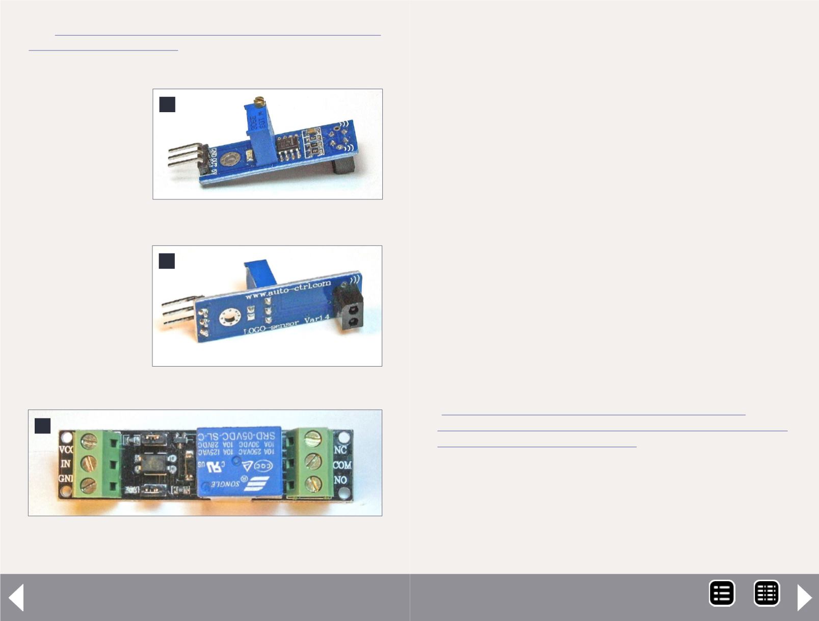
4
4. Optical reflective sensor module.
5
5. The sensor side of the module.
See:
Optical Train Detection - 6
The 1.26”x0.43”x0.79” board is dominated by a multi-turn
potentiometer on one side (which adjusts the detection range)
and on the other by the source/detector pair. Figure [4] shows
the potentiometer side and [5] shows the emitter/detector side
of the module.
This module has a hole that can be used for mounting. Hookup
is via a three pin “header” on one end consisting of +5V, ground
and output pins. In use, the source/detector pair would be
inserted facing upward between the ties. When powered up and
an object passes within the detection range the output pin goes
to “logic low” (computer ‘logic low’ is between 0V and 0.8V).
Connecting to a signal system
If your signal system can accept logic-level signals, then you
supply power to the module, run the output to your signal
system and you’re done.
But most signal systems are set up to detect a switch closure.
In which case another module is needed. On eBay I found the
following module which goes by the equally awkward name
of “DC 5V Relay Control Panel Controller Module with Optical
Isolator”; item #280823518850, from vendor “bosity”; price:
$4.99
.
This 2.8 x 0.7 x 0.8 inch module has a 10 amp SPDT relay and
the interface circuitry necessary to read a logic low signal at it’s
input. One end of the relay module has +5V (on the terminal
marked VCC), ground and input screw terminals. On the oppo-
site end are screw terminals for the normally open, normally
closed and common connections to the relay [6].
6
6. The DC 5V relay control panel controller module with
optical isolator.
MRH-May 2014


