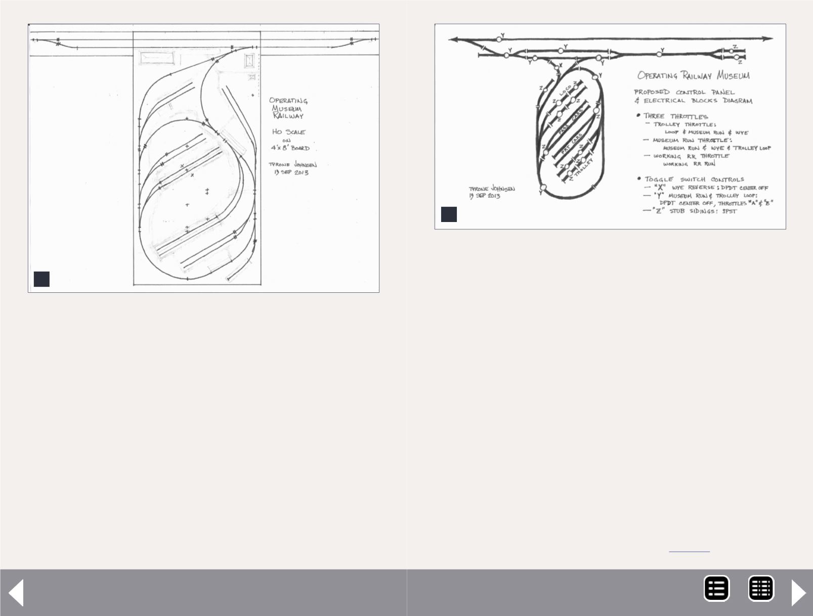
6. Layout plan for HO scale on the 4x8 tabletop.
6
$500 layout grand prize - 5
Layout control
The layout throttles will be DC, with two-position toggle
switches to control the electrical blocks. The eventual con-
trol panel will be done on in the conventional manner, using
hardboard mounted into a used computer keyboard drawer
installed under the layout table hear the edge of the wye
throat. It can be slid under the layout when not in use. Three
DC throttles will eventually be used, one mainly for the trolleys,
one for the museum steam, diesel, and interurban runs out
and on the straight run, and an optional third one to handle
the working UP line.
I will start with a standard stationary “power pack,” which can
continue to function for the trolley loop. But I would like to
7. Envisioned control panel and block toggle switches.
7
build or buy a corded throttle for the straight run. Figure 7 illus-
trates my proposed control panel layout, with the location of
track rail insulators defining block limits, and the style of toggle
switches to be used. To start, only one DPDT center-off switch is
required, and that is to control the polarity of the reversing sec-
tion of the track wye. The other switches may be added as addi-
tional throttles become available. All toggle switches might be
DPDT center-off switches but all stub tracks require only a SPST
on-off switch. Only one rail gapped, and more storage blocks
than the two shown per stub will be desired. Wiring is all con-
ventional, and space here does not permit covering it in detail.
Although I am not able to duplicate the IRM, I believe it is desir-
able to try to understand it to a reasonable level, in order to
make my layout appearance and operation believable. Even in
N scale, the loop would require the layout table to be twice the
width and length, and the five-mile run would require 165 real
feet. I continually refer to the IRM website,
where they
MRH-May 2014


