The initial build took a little over eight months. I began with
three pieces of 2” pink foam glued together. I had to add two
more pieces later to keep the module from bending and break-
ing the bridge parts. I molded the land to fit the bridge, apply-
ing the measurements taken of the prototype.
The wooden part of the bridge was built first. I had to first
build a jig to fit the complicated pieces together. Ken Patterson
loaned me his HO-scale caliper to measure the scale lumber.
Next was the steel girder bridge section. This was accom-
plished by cutting down two Central Valley girder bridges and
attaching them together.
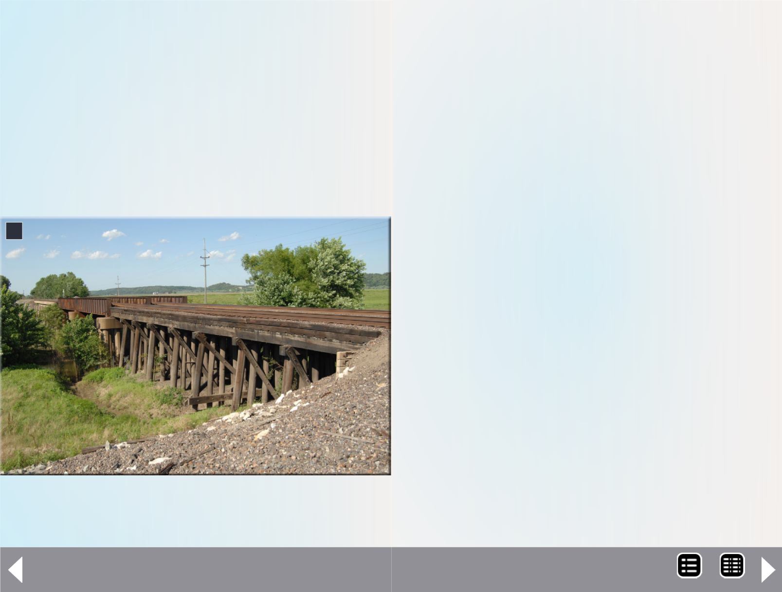
7. The wooden trestle supporting the approach span contrasts
with modern segmental concrete work supporting the steel
through-deck bridge. Dirk Reynolds photo.
7
What’s neat column - 6
The bridge pilings were donated by Scale Segmental Bridge
Company. They have the true octagon shape, like a stop sign.
I ran into a problem with the casting of plaster they are made
from. They are very fragile. My solution was to cut down square
wood pieces into eight-sided pieces, without cutting my fingers.
I then encountered the same problem Union Pacific’s bridge
builders had when they built the first side in 1982. The other
side was completed in 1983, as shown by the cornerstone
dates in the bridge piers. I knew the length of the bridge, but
this did not match up on the north side. I knew I needed seven
bridge segments, but this did not add up right to reach the
girder section. I then learned why they used I-beams to span
the gap. The eighth segment was too short. Notice the short
red segment to the left of the main span in the lead photo on
the previous pages.
This is also why I wanted to model this particular bridge, since
my photos show four different types of bridge spans in its
consist. Now, unfortunately, it has been retrofitted, and con-
tains only three types of the modern concrete type segments
and a lot less personality.
This type of bridge uses “floating ballast track.” This means the
ballast literally holds the track in place while it floats inside the
bridge deck segments. In modeling, however, you have to use
a different approach to laying the track. I made the mistake of
trying to lay the track on wood and then liquid ballast it. What
a disaster! I had to rip up three hours of work, rebuild the
wooden section with styrene, silicone the track to it, and then
liquid ballast it down.
The concrete section also worked differently. The prototype
track is placed inside the segments. On the model, the track is
on top of the ballast while inside the segments. A bit of painting
MRH-May 2014


