DCC Impulses Column - 3
heat in the amplifier. This added heat can damage or destroy
the decoder, depending upon the amplifier design.
Higher impedance (say 16 ohms) will reduce the load on the
amplifier, but the amplifier may not be able to push as much
power into the lower load: 3/4 watt into 16 ohms would be
a common result. Generally, higher impedance loads are not
harmful to the decoder; you just reach a point where the
diminished audio power isn't compensated by the increased
efficiency of adding more speakers.
I recommend checking with the decoder manufacturer before
you contemplate any impedance other than the rated load, be
it a single value or a range
of loads.
Heat
Be aware, as we make
smaller and more power-
ful (both electrically and
feature-wise) decoders,
heat generated inside the
decoders becomes more
of an issue. How the heat
will get out of the decoder
should be a design cri-
terion in every installa-
tion. With small sound
decoders, it becomes very
important. If you are con-
templating pushing the
envelope on load imped-
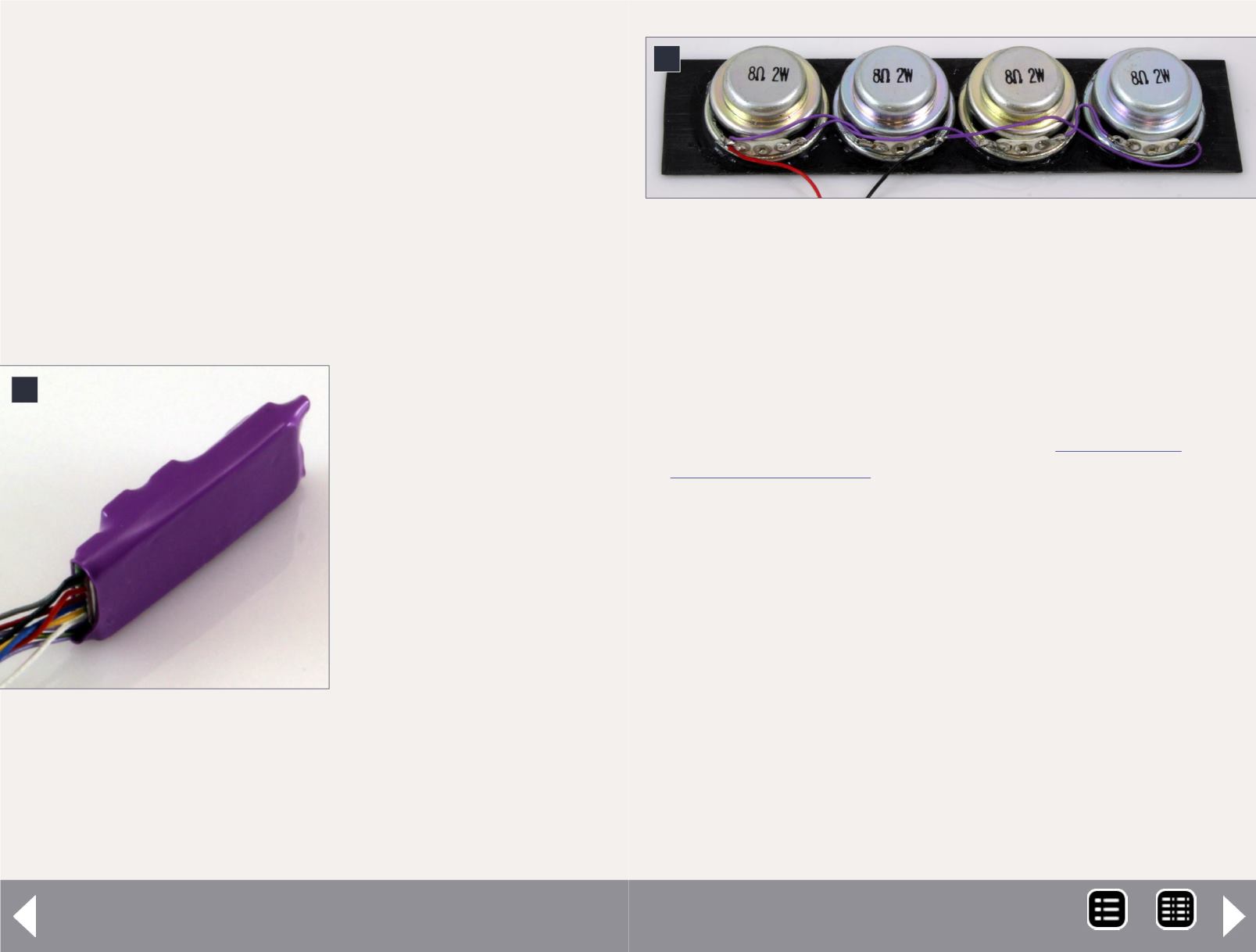
4: Line array of four identical speakers - wired in a series-
parallel combination, the resulting unit is rated at 8 ohms
and 8 watts.
3: TSU-750 Micro Tsunami,
showing flat side where the in-
ternal heat sink is located. This
should be attached to a metal
surface to remove heat from
the decoder.
3
ance (4 ohms on a decoder rated for a nominal 8 ohms), then
heat may become an even bigger issue.
Figure 2 shows a mounting plate for a TSU-750 micro Tsunami I
built out of brass sheets held together with thermally conduc-
tive epoxy (see my December 2012 column -
. Brass sheets (0.032” thick) were cut
to the size of the top of the frame where the driveline went
between the motor and the front gear tower. They are stacked
up until they are tall enough to clear the gear tower at the
limits of its height when pivoting and swinging. Then a single
sheet is glued extending forward to provide a decoder mount-
ing location. In the photo, a bit of white epoxy is visible where
the decoder mounts. I had previously mounted a decoder on
this stack, and removed it by light prying. The Alumina Thermal
adhesive broke cleanly away from the decoder shrink tubing.
A dab of thermally conductive epoxy and the decoder will be
back in place – flat side against the brass plate.
So how does this work? The components inside the decoder
that need to be cooled are connected through thermally con-
ductive foam to a metal plate that is held in place with the
4
MRH-Jan 2014


