DCC Impulses Column - 8
From Mr. DCC’s workbench
How do I switch more current with my
decoder?
Occasionally there is a need to switch a load that isn’t
compatible with the output of a DCC decoder. Whether this
need is due to the voltage or current needed, or if a contact
closure (or opening) is needed, it can frequently be filled by
using a relay.
A relay is an electro-mechanical device that takes some
electrical current and uses the resulting magnetic field to
move some contacts, just like throwing a switch. There is a
mechanical lag time while the contacts physically move, so
they are not well suited for items that get turned on and off
quickly. Likewise, they don’t do dimming, just on and off, so no
fancy lighting effects, either.
Sounds easy, just connect the relay to the blue and green (or
other function) wire and be done with it, right? Uh, no, not
actually.
Think about the spark coil that generates thousands of volts
to ignite the gasoline in our car engines. They work on the
concept of turning the current on and off through a coil.
Similarly, a relay will generate a large spike of voltage when the
current is turned off. This spike is enough to blow the output
transistor (and, perhaps, more circuitry) inside the decoder if
the relay is hooked up directly to the decoder.
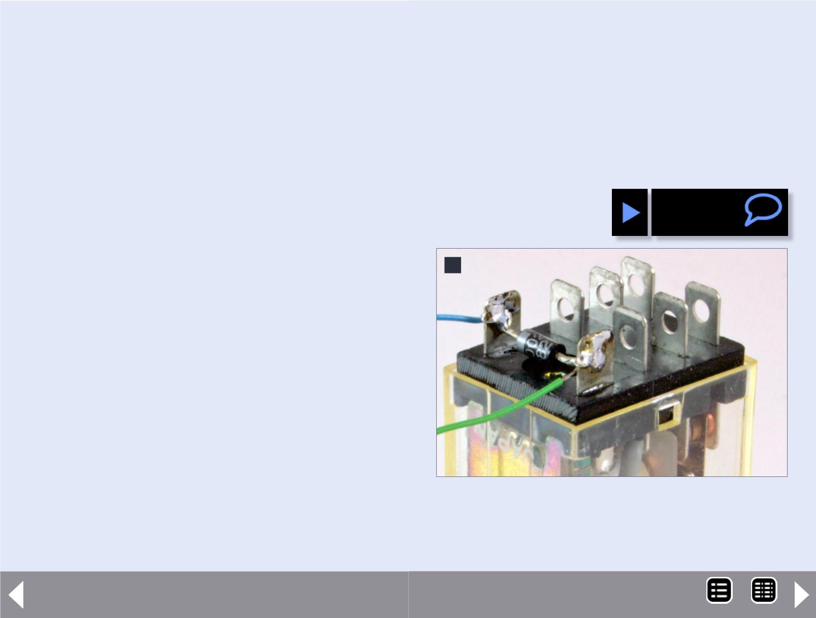
A simple diode will fix the problem. It is put across (in parallel
with) the relay coil in a direction where the normal current will
flow through the coil, but when the current is turned off, the
spike of voltage goes through the diode. This means that the
end of the diode with the band connects to the blue (or positive)
wire from the decoder as shown in the detail photo, figure 9.
Select a relay with a coil voltage of 12 volts and an activation
current less than the decoder function output is rated for.
Frequently the functions are rated for 100 mA (0.1 A), so a
coil resistance above 150 ohms is needed. Make sure the
contacts are rated for voltages and currents higher than you
are going to be switching.
9: A diode protects the decoder from being damaged
by the high voltage spike when the decoder drops
the current to the coil. Note: diode band is toward
blue wire. Photo by the author.
9
MRH-Oct 2013


