STEP 10A: The Ends for the 76500 – 76999 Series
Continued ...
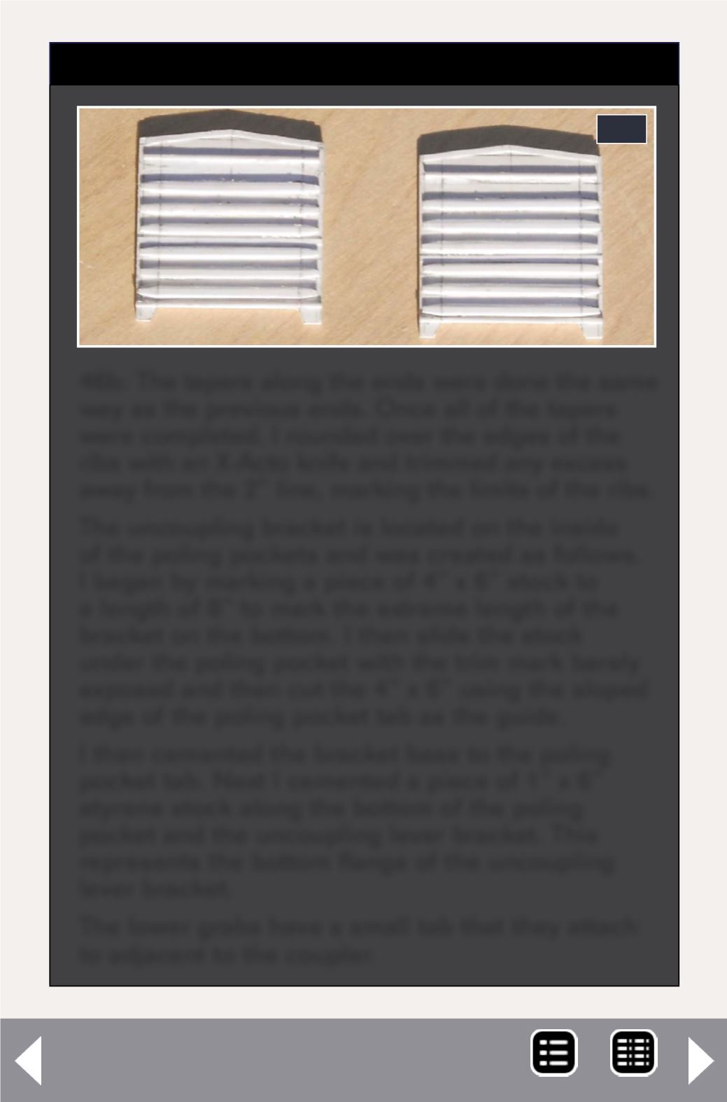
46b
46b: The tapers along the ends were done the same
way as the previous ends. Once all of the tapers
were completed, I rounded over the edges of the
ribs with an X-Acto knife and trimmed any excess
away from the 2” line, marking the limits of the ribs.
The uncoupling bracket is located on the inside
of the poling pockets and was created as follows.
I began by marking a piece of 4” x 6” stock to
a length of 8” to mark the extreme length of the
bracket on the bottom. I then slide the stock
under the poling pocket with the trim mark barely
exposed and then cut the 4” x 6” using the sloped
edge of the poling pocket tab as the guide.
I then cemented the bracket base to the poling
pocket tab. Next I cemented a piece of 1” x 6”
styrene stock along the bottom of the poling
pocket and the uncoupling lever bracket. This
represents the bottom flange of the uncoupling
lever bracket.
The lower grabs have a small tab that they attach
to adjacent to the coupler.


