this data to the microprocessor allows it to adjust the width of
future pulses based on the current speed of the motor, creat-
ing a feedback control system.
Various manufacturers utilize this in many different ways. Some
allow the user to select a speed step beyond which the BEMF
doesn’t change the motor pulses, i.e. “BEMF Cutoff”. Some
allow the user to adjust the various components of the feed-
back control system.
BEMF control needs a BEMF detector connected across the
gray and orange wires. When the microprocessor tells the
BEMF detector that the motor is off, then the detector reads
the voltage from the motor and translates that into a digital
value, which is sent to the microprocessor. This circuitry is not
shown in figure 3, to keep the complexity of that figure down.
8
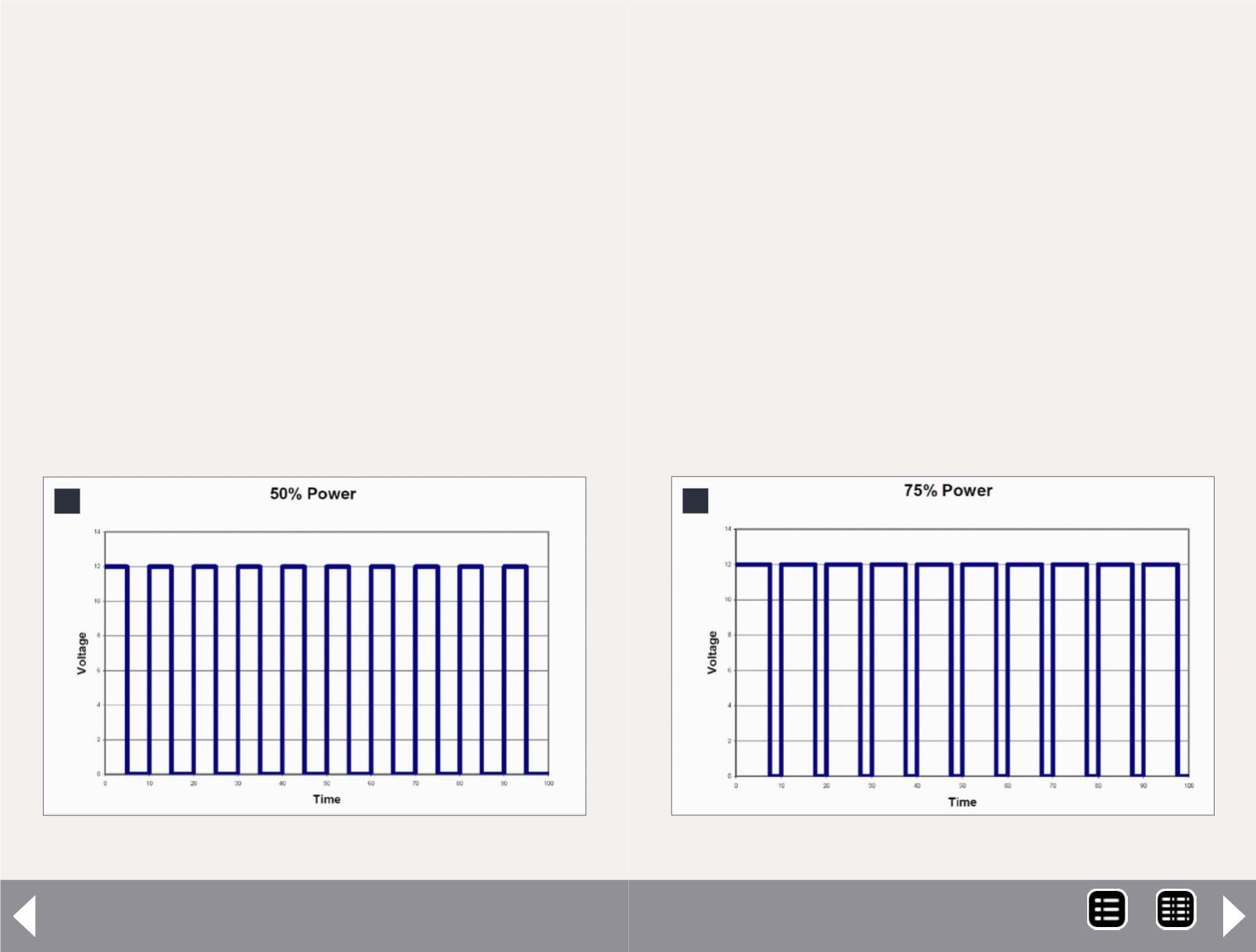
8: Motor voltage pulses at 50% power going forward.
DCC Impulses Column - 6
Dither (motor control)
The disadvantage of driving the motor at a frequency above
human hearing is that there is a loss of drive (torque) from the
motor at low speeds. A solution for this loss was found. If the
motor pulses are not exactly on time, much of the lost torque
is regained.
Think of a teen-age garage band. They might be able to play a
hit song, but they can’t all stay on the beat. Assume that the
drummer is spot-on with his beat, but sometimes the singer is
ahead of him and some times behind. Various decoder manu-
facturers call this variation around the “correct” time “dither”
or “torque compensation”.
Yes, it is possible to have dither and BEMF in the same decoder.
The current offerings from TCS and others do so.
9
9: Motor voltage pulses at 75% power going forward.
MRH-Feb 2013


