Anatomy of a DCC Decoder
Looking at what’s on that little board
L
ast month’s column about sound installation in a
HO-scale Kato NW2 was long and detailed. That
column, and the companion video (
, was the
culmination of many months of work. Hopefully you found
some hint or idea in there that you can apply to your pike.
This month’s column will be a bit less ambitious. I’m going
to delve into a topic for every DCC user: what is going on
inside the decoders we use and how to make the best use of
what you are provided, internally and externally.
If you need a refresher course in DCC Basics, you may wish
to review my inaugural column from October 2011
.
DCC Impulses column
by Bruce Petrarca
Understanding what is inside will help your
installations ...
DCC Impulses Column - 1
What is happening
Functionally, the decoder takes (packets of) data off the track and
uses them to decide what to do: drive a motor, turn on lights,
generate sounds, etc. Let’s look inside and see the basic functions
necessary to make all of this happen.
When I reference colors of wire, I’ll use NMRA recommended
practices wherever they are defined. For the less well defined, I’ll
use industry practices to explain the situation.
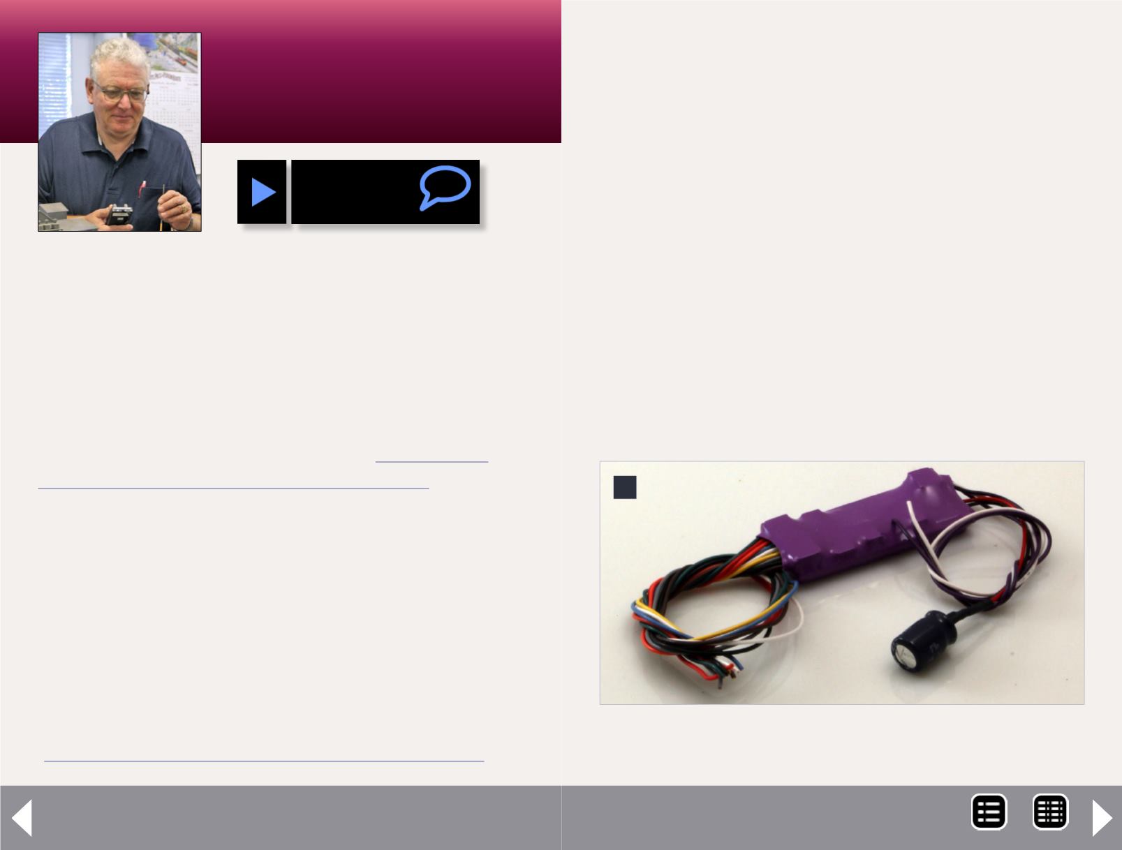
There are two basic styles of decoders: wrapped and open boards.
The wrapped units (1) have shrink tubing surrounding the
decoder board with wires coming out of one or both ends.
When I talk about wiring colors in this column, I’ll be referring to
this style of decoder.
Open board decoders (2) don’t have the shrink tubing and fre-
quently have contact points for wiring connections. The con-
nection points are labeled or referenced in the instructions
with this style of decoder.
1: Wrapped decoder example – SoundTraxx Tsunami
TSU-1000.
1
MRH-Feb 2013


