If you remember my December 2012 column on Basic Electronics
, two parallel conductors separated
by an insulator make a capacitor. Well, your locomotive’s wheel
and the track, separated by insulating dirt, make a capacitor.
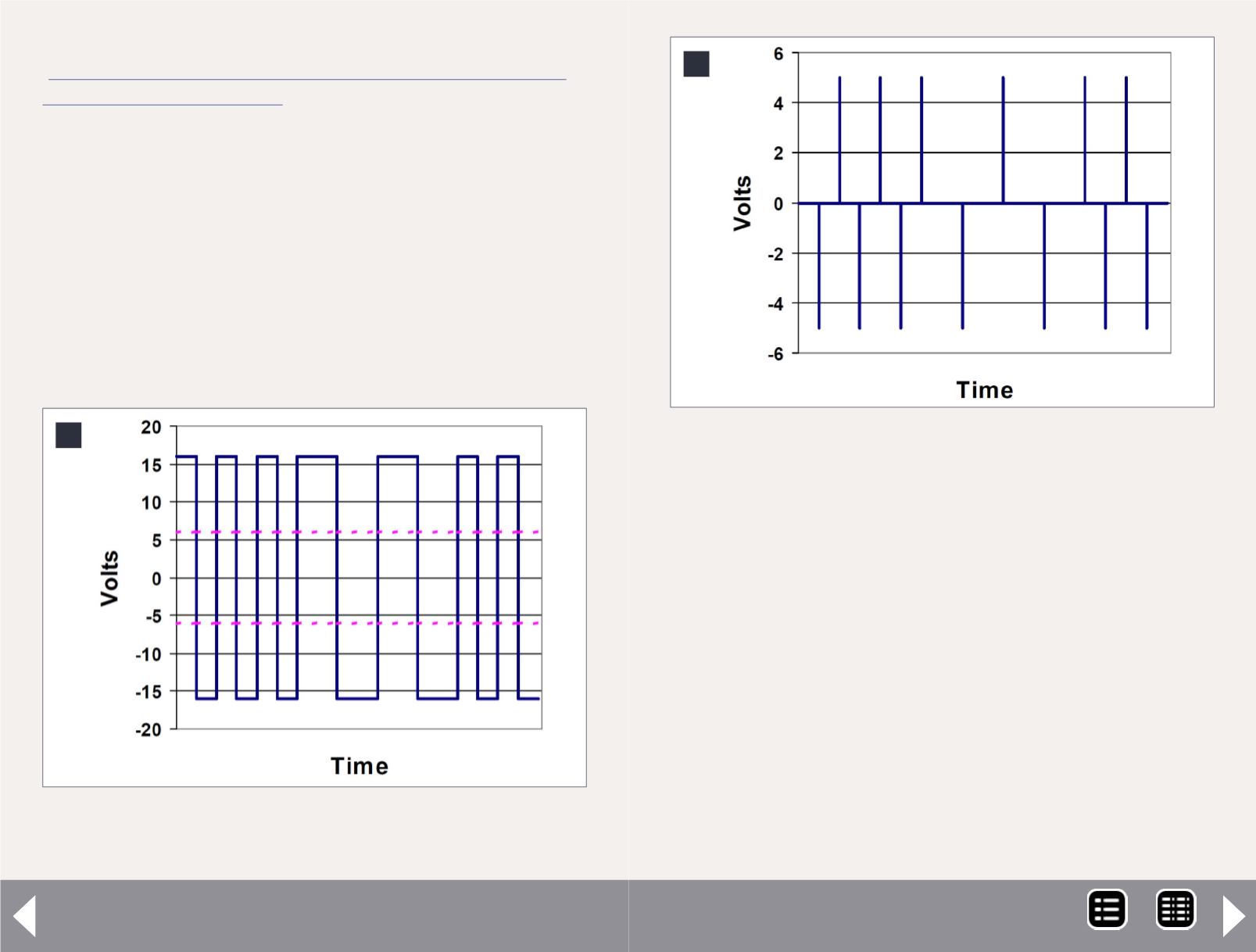
So, if your detector is designed to decode the signal in figure 6
and your loco runs over a dirty spot on the track, the amplitude
of the (6) signal will diminish, but the shape of the waveform
won’t change. Thus, the decoder can read the DCC signal even
through a sheet of paper. If you are detecting signal level (5)
the sheet of paper will reduce the level to zero and the decoder
won’t see any transitions.
Either detector will create a data stream for the microprocessor
to analyze and act upon.
5: Threshold Detection – looking for when the DCC sig-
nal goes through 6 volts – DCC data = 111111000011.
5
DCC Impulses Column - 4
Microprocessor
The block in figure 3, labeled Micro Processor, includes a lot of
things, including the memory where the program and sound
files are stored and the clock that keeps time for everybody. I
lumped them together, as many times the microprocessor chip
will have built in memory and the clock is typically not con-
nected elsewhere.
Here is some of what the microprocessor is doing almost
simultaneously:
Interpreting DCC commands
Calculating motor speed and direction
Creating motor drive pulses
6: Transition Detection – looking at the change in the
DCC signal – DCC data = 111111000011.
6
MRH-Feb 2013


