flywheel. Too much cutting here and you’ll cut through the
frame (ask me how I know this).
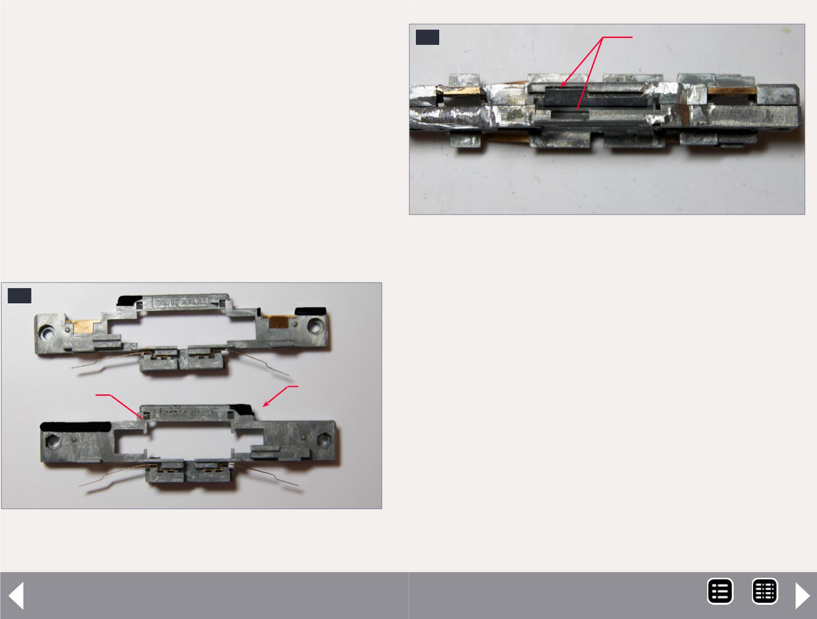
After you are done, insulate the area of the frame where the
motor contact strips come up to contact the circuit board. I
use Kapton tape for this. We won’t be using the circuit board,
so you want to make sure these strips can’t accidentally con-
tact the frame and cause a short.
Photos [20-22] show the cut frame. The speaker will go on
the rear of the frame, and the frame is reassembled with the
motor inside and the Kapton tape insulating the areas around
the motor contact strips.
The last prep step is to cut a small piece of old circuit board to
solder the decoder power pickup wires.
That’s it for the prep steps. Now it is time to install the decoder,
headlight LED, and speaker.
Final assembly and wiring
Cut the LokSound wires to the right length. The exact length
will depend a bit on the exact placement of the decoder on the
frame, but the orange wire is about 20 mm; the gray about 22
mm; the red and black about 32 mm. Then I strip the ends of
the wires and tin them with solder.
Before installing the decoder, I install the surface-mount LED
for the front headlight. I use a sunny white SMT LED from
Richmond Controls that comes with 6” fine magnet wire
attached. You want just enough wire to loop at the end of the
“channel” in the top part of the frame and hook to the white
and blue wires.
18
18. The black areas show where the frame needs to
be milled.
N scale sound - 7
Don’t cut to close to the fly-
wheel cutout.
Be careful cutting
around this hole
19
19. The milled frame showing the locations of the
Kapton tape.
Place Kapton tape
around these openings
MRH-Dec 2014


