Building the actual track lay-
out causes some adjustments
and creates some opportunities. I solder about foot-long sec-
tions of electrical wire to the bottom of each metal rail joiner
prior to using them to connect track. In some cases, I need to
connect wires to the rails. Practice is needed to minimize dam-
age to the track. Peco does show some connection clips which
might be interesting to try.
The DPDT switch will control the polarity of the tight curved
reversing section of the wye. Some temporary method of fas-
tening this switch (e.g., tape, glue, or a small board) will be used
until a control panel is made at a later time. The electrical wires
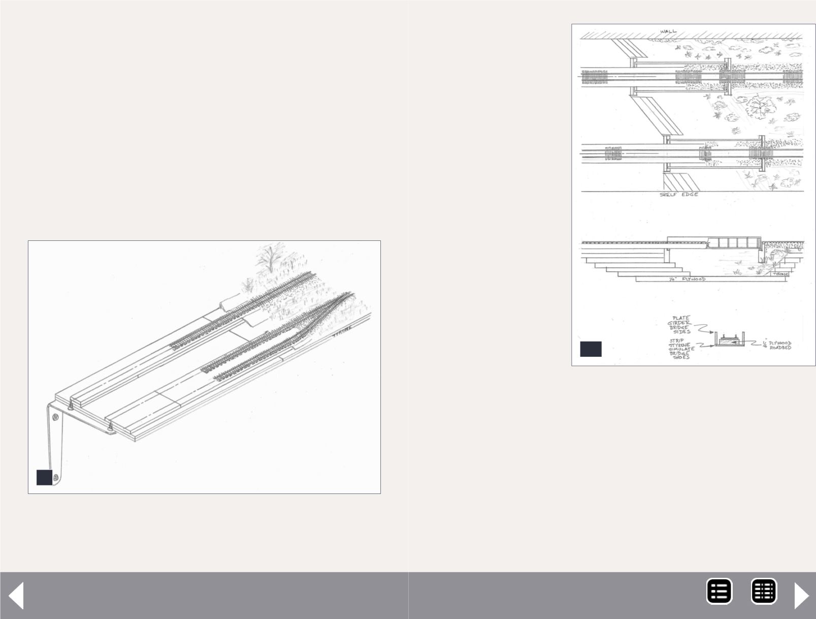
9. This sketch shows my proposed construction of
the shelf layout portion. I plan to use “L” brackets to
support the shelf.
9
$500 layout grand prize - 9
from the rails and rail
joiners are generally
run above the board,
eliminating the prob-
lem of drilling through
the door panel. The
wires are held in place
with quick-tack glue,
and will be eventu-
ally hidden with both
paint and ballast ,and
other scenery.
Layout
construction
I cut some of the ply-
wood into 8”-wide
strips, six of them 4’
long each. Cutting off
the 4’ ends is easier
for me to work with
and to cut with my
hand saw. I also cut
one 4’ strip 2.25”
wide and three at 1”
wide. The first set will
become the shelves
when laminated to double thickness. The last narrower strips
are the roadbed. The wider roadbed is for the double-track
sections, and the narrower is for the single track.
These are then laminated in an overlapping fashion over the
previously laminated shelves. The shelf brackets are attached
through the drywall into each stud, such that the resulting
roadbed surface was level with the door panel top surface.
10. This sketch shows
construction details of the
bridge.
10
MRH-May 2014


