DCC Impulses Column - 3
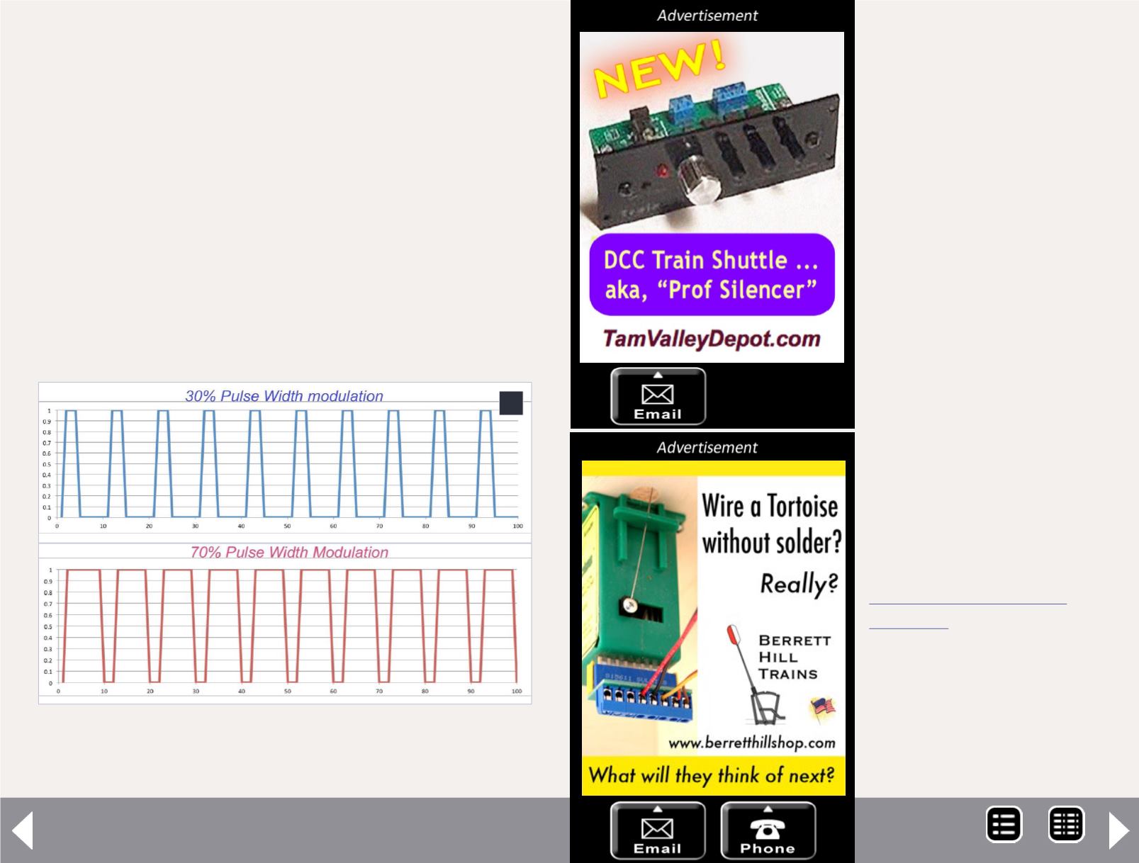
PWM is where full voltage is always applied. The voltage to
the motor is turned on and off in repetitive pulses. The lon-
ger the pulses, the faster the motor runs. If you want the
motor to run at half speed, the full voltage is applied for
about half the time and zero voltage the rest of the time.
Thus, you control the motor speed, not by changing the
applied voltage but by varying the time that it is applied
(that is, the Width of the Pulses).
When DCC was created, PWM was selected for many reasons
as the motor control method. Also, part of the basic DCC design
was the ability to adjust the amount of power provided to the
motor at the starting speed step (CV 2), at the middle (CV 6) and
at the top (CV 5). See figure 2.
Some decoder manufactur-
ers opted to include a feature
to overcome the stiction and
inertia by providing addi-
tional power at low throttle
settings for a bit of time.
They frequently called it kick-
start. It gave much of the
same effect as the early pulse
power packs and is adjust-
able in some brands.
As DCC became popular and
more and more locos began
running with decoders, folks
began to notice that the
locomotive would hum at
the frequency of the pulses,
usually in the octave below
middle C, for the musi-
cians in the crowd. Decoder
manufacturers responded
with high frequency drive
where the pulses
were so rapid that any "sing-
ing" of the motor was beyond
human hearing, some as high
as 30 kHz. Each manufacturer
has its own marketing moni-
ker for this design.
2
2: PWM – full voltage, variable time driving a motor at
30% and 70%.
MRH-Dec 2013


