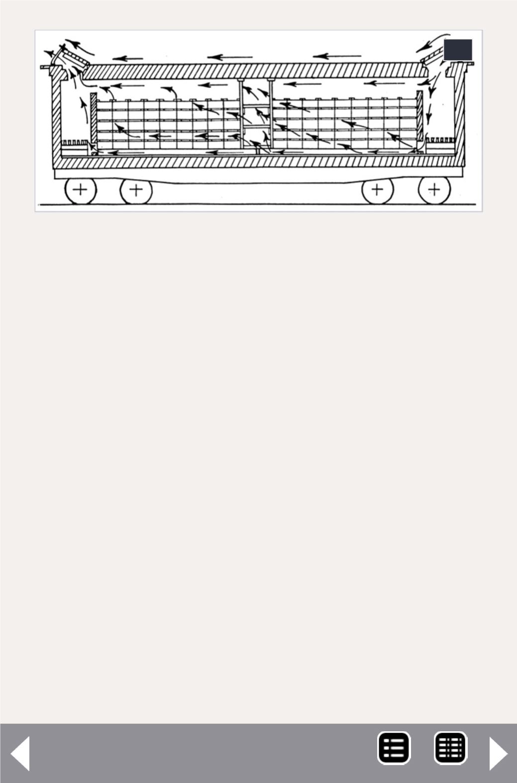
12: This SP diagram shows air flow through a car set
up for ventilation service. Note that the load does not
reach to the car ceiling, to help with air flow, and that
dunnage at the car center will allow easier unloading.
– Author’s collection.
12
locations only, or any other of a variety arrangements. In cooler
weather, when less ice would be consumed, stage icing could
be chosen. This meant setting ice grates at half height in the
bunker, so that filling to the top with ice would leave the bot-
tom half of the bunker empty (see Figure 2). This maintained
good air circulation, while allowing all cars to be re-iced the
same way: filling the bunkers to the top.
At an icing deck, foremen would go down the string of cars,
opening ice hatches and estimating by eye the amount of ice
needed to fill the bunker to the top. They noted this on a clip-
board as they went from car to car. The ice usage for each car
was charged to the freight bill for the car. Occasionally the
ICC would conduct a field test, checking how accurate these
foreman’s estimates were, and they were usually found to be
quite accurate.
The process would continue all the way to the car’s desti-
nation. Many cars were directed to eastern or midwestern
contents


