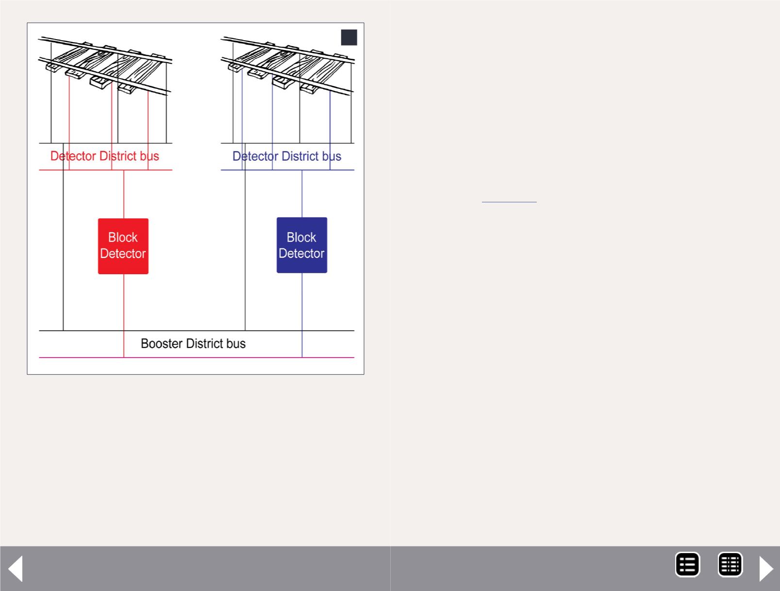
1: Wiring detection district buses to the booster dis-
trict bus.
1
Districts
One of the first things that folks encounter when moving from
DC to DCC is revising their terminology. No longer do folks talk
about blocks. In the DCC world, there are power districts: a sec-
tion of track that is isolated from the rest of the layout and driven
through some sort of power manager or electronic circuit breaker.
Reasons for this isolation include:
Troubleshooting (isolating where a short is on the layout).
Power distribution (supplying enough power to the entire
layout to support all the locos moving at one time).
Job isolation (if Sam runs a turnout on his job and takes
down part of the layout, Dave can still run).
Within a power district, there may be sections of track that you
want to detect individually. For example, on our PebbleCreek
club layout
, we have nine tracks in double-ended-
hidden staging, all in one power district, see figure 8. Each of
these nine tracks, as well as the incoming and outgoing leads
are detected, so we can tell what is happening without hav-
ing to look under the layout. Each of these 11 sections of track
might be a block on a DC layout. To avoid confusion, I’ll call
them detection districts, not blocks. I’ll refer to the wires that
feed the detectors as booster districts.
Figure 1 shows a two detection district buses (red and blue)
wired to a booster bus. One side of the rail is represented
by black wiring and is connected between all buses. The red
detection district bus has power coming to it from the other
booster bus wire (indicated by a purple color, a mixture of red
and blue) through a block detector. Similarly, the purple detec-
tion district has power coming through its own block detector.
All of the track feeders in a detection district come down to the
bus for that district.
Understand that a booster district may include one or more
detection districts. However, a detection district cannot be part
DCC Impulses - 2
MRH-Aug 2013


