9
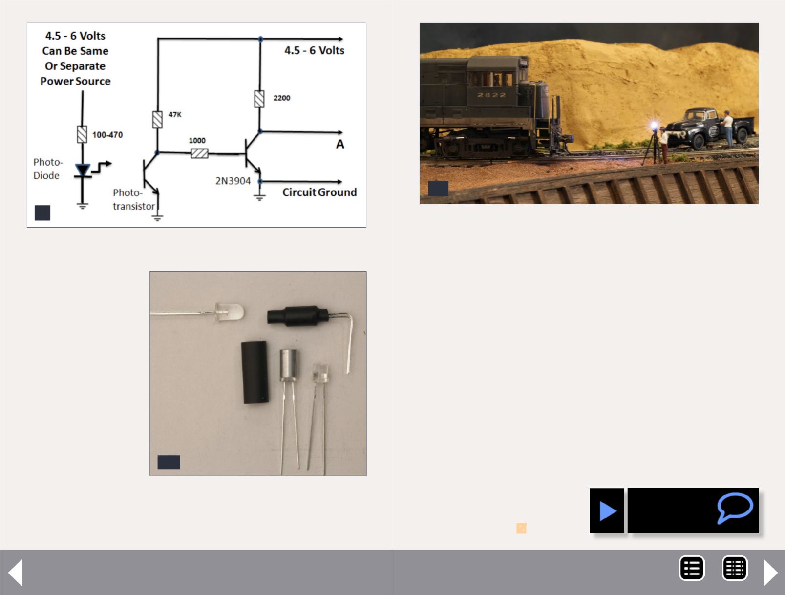
9. Infrared detector circuit.
Scale flash photography - 4
10. Infrared switch components,
LED on the left, phototransistor on
the right.
10
maintenance, and
its light is invis-
ible, allowing you
to hide it in your
scenery.
Most component
values are not criti-
cal. The circuits are
simple enough that
they can be built
on a small solder-
less breadboard.
If you use other
components, some
adjustment to the
resistor values may
be necessary. The components and values were the ones I used
and measured.
If you use the infrared phototransistor and LED, cover the end
of the phototransistor with a shield made from an appropri-
ately sized piece of ½ inch long metal tubing – I tried plastic
but it did a poor job. Glue the shield in place and then cover
the assembly with some heat-shrink tubing or tape. This will
make the transistor sensor directional and less sensitive to
picking up ambient light. Since you can’t see the infrared
light, pay close attention to placing the powered infrared LED
and the phototransistor on opposite sides of the track (where
the train will cross to break the beam) so that they point
directly at each other.
Now stand back and ask your visitors if they want any point-
ers from your company pho-
tographer as they watch him
document your road’s latest
in motive power!
11
11. The company photographer takes his last shot.
MRH-Jul 2013


