either a three cell AA battery pack or a 5‑volt “wall wart” DC
power adapter rated 200mA or better.
1.
As an alternate sensor, I use an infrared photo‐transistor
and an infrared LED. The Infrared LED is an LEDTech UT1883-
81-940. The infrared phototransistor is a matching LedTech
LT9593-91-0125 (data here:
and
. The IR diodes and
transistors are available from All Electronics
, and others from Jameco
).
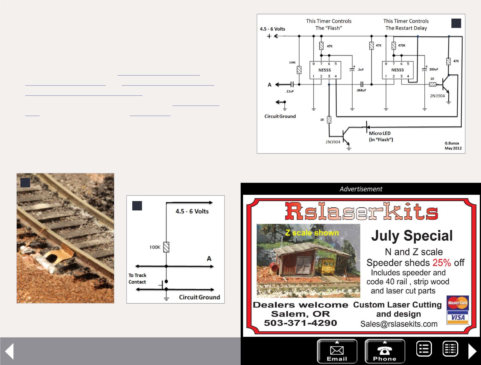
Both trigger circuits are shown in the figures below. The
mechanical contact will wear over time, and is subject to
abuse – but it is simple! The infrared solution takes longer to
set up but, unless you power it with batteries – requires no
6
6. Track mechanical
contact before burial.
Scale flash photography - 3
8. Flash timer and delay circuit schematic.
8
7. Track contact circuit.
7
MRH-Jul 2013


