to cover where the wires attach to the LED back too, to insulate
the wire contacts and strengthen the connections.
All components are mounted on a piece of perf board run-
ning the length of the body shell and screwed to the top of the
chassis. The reed switch is mounted at the highest point, in
the middle and just under the roof. I use a small magnet glued
into a box-like structure, painted the same color as the body, to
make an unobtrusive on/off switch [25]. These reed switches
have worked out so well that I have ordered more to use in
future models.
Remote control
A model loco providing its own power will no longer respond
to voltage changes on the rails (DC) or to power and signal on
the rails (DCC). In fact, battery operation is by definition (at
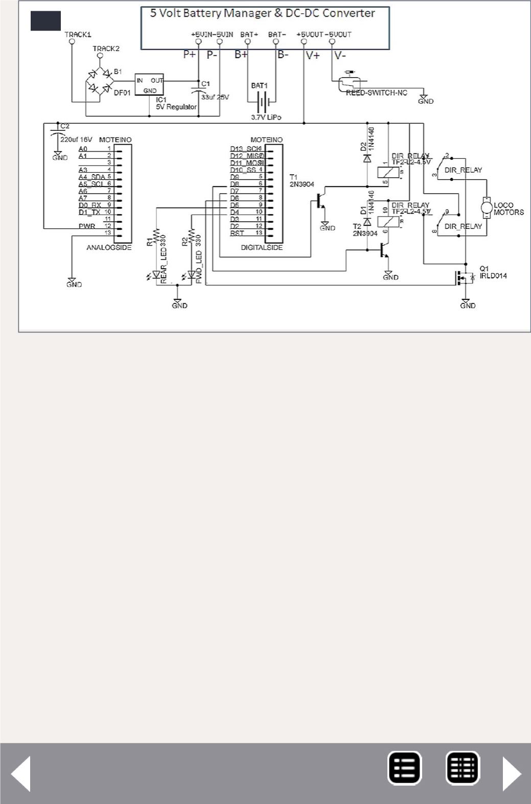
28. Locomotive battery power block diagram.
28


