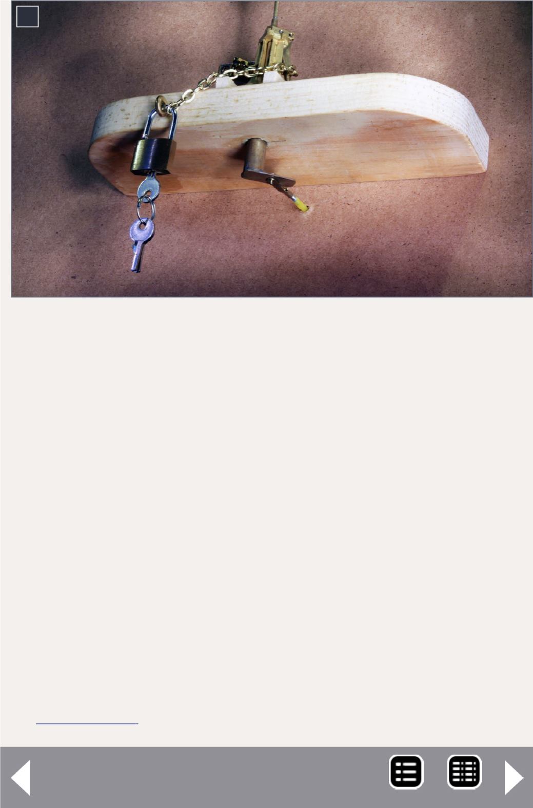
6. The modified mechanism of the switch stand
projects below the shelf to connect to plastic control
rods. The lock is an inexpensive luggage lock.
My initial thought was to connect the control cable directly to
the bottom of the stand, using a piece of steel wire between
two head blocks to represent the head bar (throw bar) on a
switch. This wire could run through a hole in the fascia to con-
nect to the control rod. But we realized this would present
some challenges.
The biggest challenge was that such an arrangement would
only give us about ¼” of throw, which wouldn’t be enough
for the BullFrog; we wanted the BullFrog’s throw to be long
enough to provide positive pressure on the points of a switch,
to hold them securely against the stock rails.
Modifying the switch stand
Chris solved the problem by fabricating an extension for the
bottom of the switch stand with brass shapes from K&S Metals
Here’s how to modify the stands:
6


