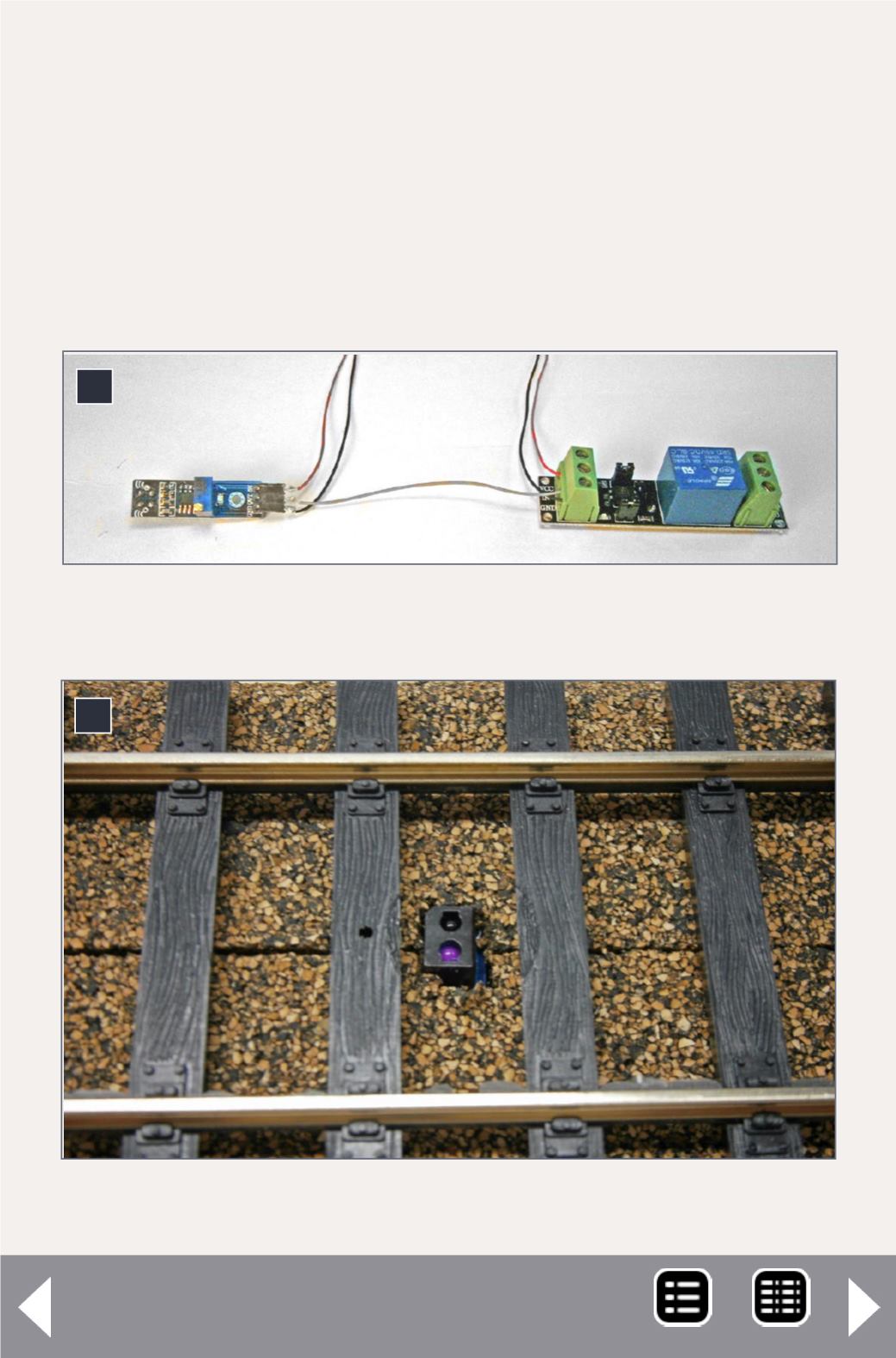
To make the two modules function together each module needs
to be supplied with regulated +5V (more on this later) and the
output from the sensor is wired to the input of the relay mod-
ule – that’s all there is to it. To prevent soldering directly to the
pins on the sensor module, I cut off 3 female sockets from a strip
of header sockets (SAMTEC BCS-130-L-S-TE, for 0.01” pins on
0.100” spacing) and soldered to the sockets.
7
7. The two modules interconnected.
8
8. The sensor mounted below the track.
Optical Train Detection - 7
MRH-May 2014


