The accompanying circuit provides the rest of the magic. It is
a simple circuit that pulses the LED with a higher than normal
current (about 75 mA measured) for a very brief time (about
8.5 milliseconds) and then waits for some longer period of time
for the train to pass. With the component values listed, this
time is about 2 minutes. It can be adjusted longer or shorter
by increasing or decreasing the 470K resistor and/or the 200uF
capacitor. Do not dramatically increase the pulse time to the
LED by fiddling with the first NE555's values, or you will blow
out the LED. This overdrive technique is used on cell phone
flash units all the time, and will reliably yield a nice bright flash.
The circuit is straightforward, and most people familiar with
electronics should be able to build it. The track "trigger" con-
sists of wires connected to a bit of a Kadee coupler box spring
hovering just above rail height. The ground (or common wire)
is connected to the rail below the track sensor. Note: do not
use track power in this case to power the flash circuit. I use
5
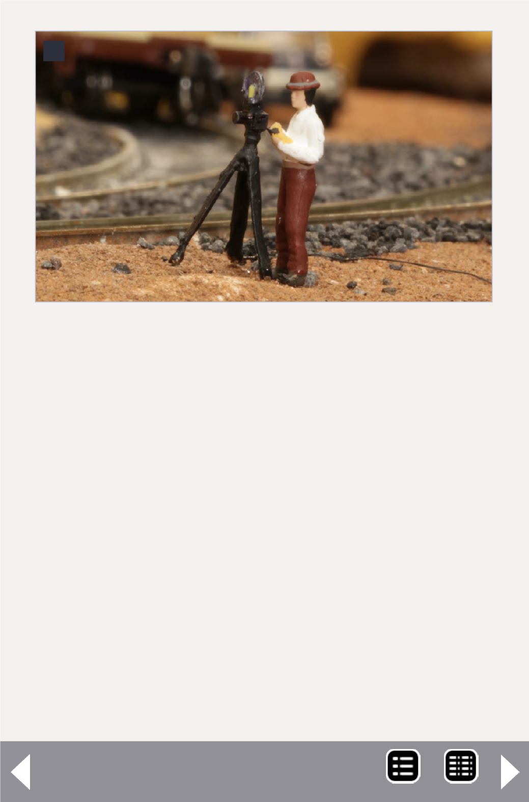
5. The company photographer Phil sets up his shot.


