this data to the microprocessor allows it to adjust the width of
future pulses based on the current speed of the motor, creat-
ing a feedback control system.
Various manufacturers utilize this in many different ways. Some
allow the user to select a speed step beyond which the BEMF
doesn’t change the motor pulses, i.e. “BEMF Cutoff”. Some
allow the user to adjust the various components of the feed-
back control system.
BEMF control needs a BEMF detector connected across the
gray and orange wires. When the microprocessor tells the
BEMF detector that the motor is off, then the detector reads
the voltage from the motor and translates that into a digital
value, which is sent to the microprocessor. This circuitry is not
shown in figure 3, to keep the complexity of that figure down.
8
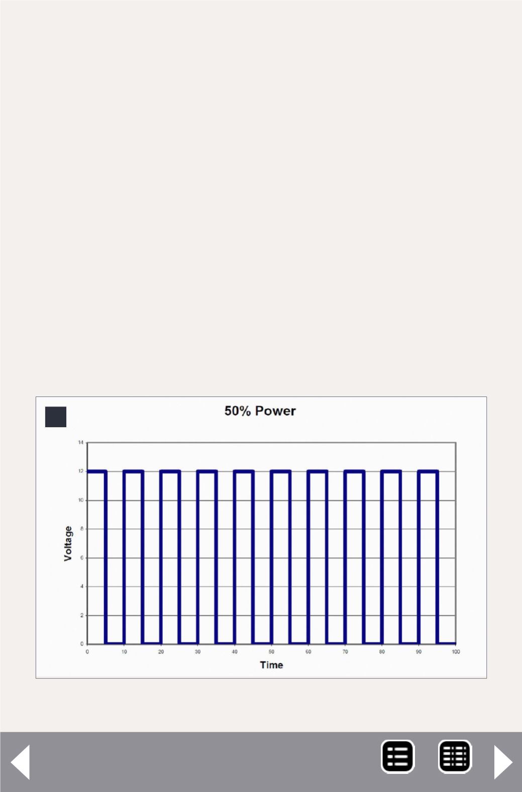
8: Motor voltage pulses at 50% power going forward.
DCC Impulses Column - 6
MRH-Feb 2013


