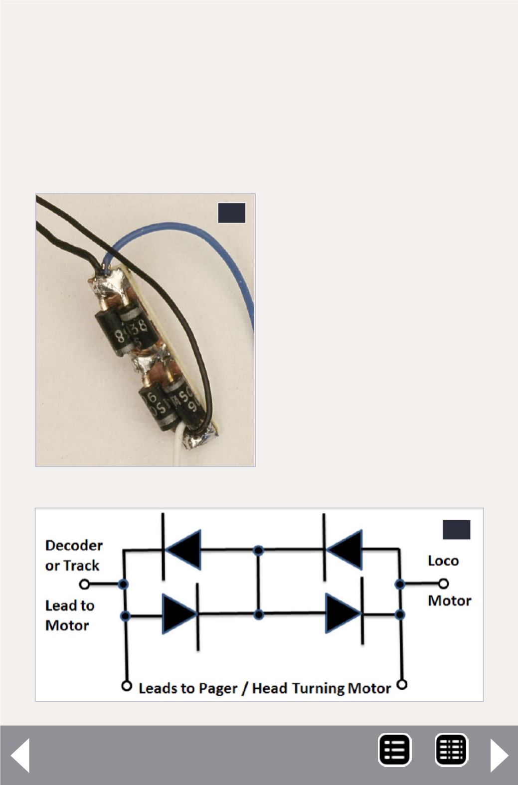
11: Diode assembly wired.
12: Diode assembly sche-
matic diagram.
11
motor is wired in the correct orientation, so the head will turn
in the direction that your locomotive is traveling! It doesn’t
matter which side of the loco motor connection you insert the
diodes. I used a small piece of single-sided printed circuit board
(or PC tie material) with cuts and holes in the copper to isolate,
mount and solder the connections. The cuts in the copper are
actually under the diodes in picture 11. I wrapped the diode
assembly in tape after all wires were attached to insulate it.
12


