3
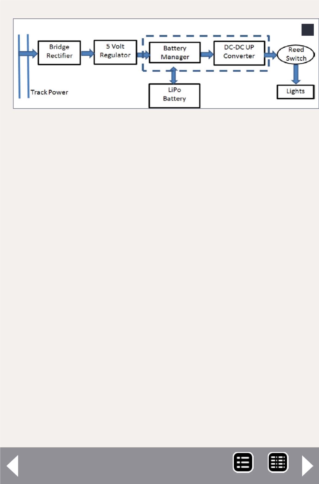
3. Basic power block diagram.
To keep things simple I elected to use a single 3.7 volt cell,
recharged from the rails. LiPo batteries have a usable voltage
range from about 3 to 4.2 volts, so part of the problem is con-
verting battery power to a usable range for model railroading.
Low cost and ease of construction were important constraints
too. The other problem is one of control. If the model is inde-
pendently powered, then how does one control it? It may be
possible to open up a DCC decoder and re-wire it, but my ulti-
mate goal was for autonomous animation applications. So, I
didn’t pursue the DCC mod approach at all.
Before getting into the aspects of control, let’s look at the basic
power source. The power block diagram is in [3]. Whatever
power is on the rails is put through a small full-wave rectifier,
regulated to 5 volts, and fed to the charging inputs of a com-
mercial battery-manager/converter board. This board prevents
overcharging the lithium polymer 240 milliamp-hour (MAH)
battery. The module also controls the charging pattern and
prevents over-discharge which can also damage the battery.
One version of the maintainer board contains a 5 volt DC-DC
converter, which provides a stable, regulated 5 volt power
source until the battery is turned off to prevent over-discharge.
This combination of components provides a stable 5 volt, .45


